HP StorageWorks Edge Switch 2/24 installation guide FW 08.01.00/HAFM SW 08.06.
Legal and notice information © Copyright 2001–2005 Hewlett-Packard Development Company, L.P. © Copyright 2003–2005 McDATA Corporation. Hewlett-Packard Company makes no warranty of any kind with regard to this material, including, but not limited to, the implied warranties of merchantability and fitness for a particular purpose. Hewlett-Packard shall not be liable for errors contained herein or for incidental or consequential damages in connection with the furnishing, performance, or use of this material.
Contents About this guide . . . . . . . . . . . . . . . Contents .................................. 9 Intended audience . . . . . . . . . . . . . . . . . . . . . . . . . . . . . . . . . . . . . . . . . . . . . . . . . . . . . . . . Related documentation . . . . . . . . . . . . . . . . . . . . . . . . . . . . . . . . . . . . . . . . . . . . . . . . . . . . . Document conventions and symbols . . . . . . . . . . . . . . . . . . . . . . . . . . . . . . . . . . . . . . . . . . . . Rack stability . . . . . . . .
LAN-connecting the Edge Switch . . . . . . . . . . . . . . . . . . . . . . . . . . . . . . . . . . . . . . . . . . . . . . Setting up the HAFM appliance . . . . . . . . . . . . . . . . . . . . . . . . . . . . . . . . . . . . . . . . . . . . . . . Recording or verifying HAFM appliance configuration information . . . . . . . . . . . . . . . . . . . . Enabling HAFM to manage the Edge Switch . . . . . . . . . . . . . . . . . . . . . . . . . . . . . . . . . . . .
Using the HAFM Basic interface . . . . . . . . . . . . . . . . . . . . . . . . . . . . . . . . . . . 69 Launching the HAFM Basic interface . . . . . . . . . . . . . . . . . . . . . . . . . . . . . . . . . . . . . . . . . . . . Setting the Edge Switch offline and online . . . . . . . . . . . . . . . . . . . . . . . . . . . . . . . . . . . . . . . . Configuring Edge Switch ports . . . . . . . . . . . . . . . . . . . . . . . . . . . . . . . . . . . . . . . . . . . . . . . . Configuring BB credit . . . . . .
Japanese notice. . . . . . . . . . . . . . . . . . . . . . . . . . . . . . . . . . . . . . . . . . . . . . . . . . . . . . . Korean notices . . . . . . . . . . . . . . . . . . . . . . . . . . . . . . . . . . . . . . . . . . . . . . . . . . . . . . . Safety . . . . . . . . . . . . . . . . . . . . . . . . . . . . . . . . . . . . . . . . . . . . . . . . . . . . . . . . . . . . . . . . Battery replacement notice . . . . . . . . . . . . . . . . . . . . . . . . . . . . . . . . . . . . . . . . . . . . . . .
8 9 10 11 12 13 14 15 16 17 18 19 20 21 22 23 24 25 26 27 28 29 30 31 32 33 34 35 36 37 38 39 40 41 42 43 44 45 46 47 48 49 50 51 52 53 Attaching the slide rail to the Edge Switch . . . . . . . . . . . . . . . . . . . . . . . . . . . . . . . . . . . . . 28 Connection Description dialog box . . . . . . . . . . . . . . . . . . . . . . . . . . . . . . . . . . . . . . . . . . 32 Connect To dialog box. . . . . . . . . . . . . . . . . . . . . . . . . . . . . . . . . . . . . . . . . . . . . . . . . . .
54 55 56 57 58 59 60 61 Tables 1 2 3 4 5 6 7 8 9 10 8 Port Binding view. . . . . . . . . . . . . . . . . . . . . . . . . . . . . . . . . . . . . . . . . . . . . . . . . . . . . . . 88 Firmware Library dialog box . . . . . . . . . . . . . . . . . . . . . . . . . . . . . . . . . . . . . . . . . . . . . . . 91 Firmware Library dialog box . . . . . . . . . . . . . . . . . . . . . . . . . . . . . . . . . . . . . . . . . . . . . . . 93 New Firmware Version dialog box . . . . . . . . . . . . . . . . . . . . . .
About this guide This guide provides information about: • Installing the HP StorageWorks Edge Switch 2/24 (Edge Switch) • Performing initial configuration of the Edge Switch Intended audience This guide is intended for individuals responsible for installing, configuring, and maintaining Edge Switches, and who are familiar with: • Fibre Channel technology • HP StorageWorks Fibre Channel switches Related documentation For a list of corresponding documentation included with this product, see the “Related doc
Document conventions and symbols Document conventions Table 1 Convention Element Medium blue text: Figure 1 Cross-reference links and e-mail addresses Medium blue, underlined text (http://www.hp.
TIP: Provides helpful hints and shortcuts. Rack stability WARNING! To reduce the risk of personal injury or damage to equipment: • Extend leveling jacks to the floor. • Ensure that the full weight of the rack rests on the leveling jacks. • Install stabilizing feet on the rack. • In multiple-rack installations, secure racks together. • Extend only one rack component at a time. Racks may become unstable if more than one component is extended.
Helpful web sites For other product information, see the following HP web sites: • http://www.hp.com • http://www.hp.com/go/storage • http://www.hp.com/support/ • http://www.docs.hp.
1 Introduction to the Edge Switch 2/24 This chapter describes the HP StorageWorks Edge Switch 2/24 (Edge Switch) and includes the following topics: • Edge Switch description, page 13 • Edge Switch features, page 14 • Hardware components, page 17 • Tools and test equipment, page 20 • Optional kits, page 22 Edge Switch description The Edge Switch 2/24 provides: • Dynamic switched connections between Fibre Channel servers and devices in a storage area network (SAN) environment, including: • Data connection a
Multiple switches and the High Availability Fabric Manager (HAFM) appliance communicate on a local area network (LAN) through one or more 10Base-T Ethernet hubs.
Error detection, reporting, and serviceability The Edge Switch provides the following error-detection, reporting, and serviceability features: • Light-emitting diodes (LEDs) on Edge Switch FRUs and adjacent to Fibre Channel ports that provide visual indicators of hardware status or malfunctions. • FRUs—small form-factor pluggable (SFP) optical transceivers, power supplies, and cooling fans that are removed or replaced without disrupting Edge Switch or Fibre Channel link operation.
NOTE: For more information about SNMP support provided by HP products, see the HP StorageWorks SNMP reference guide for Directors and Edge Switches. Zoning The Edge Switch supports a name server zoning feature that partitions attached devices into restricted-access groups called zones. Devices in the same zone can recognize and communicate with each other through switched port-to-port connections. Devices in separate zones cannot communicate with each other.
Hardware components This section describes the Edge Switch 2/24 main hardware components. Front panel Figure 1 shows the front of the Edge Switch and identifies the front panel components.
• Initial machine load (IML) button When the IML button is pressed and held for three seconds, the Edge Switch performs an IML procedure that takes approximately 30 seconds and resets the following: • Microprocessor and functional logic for the control processor (CTP) (and firmware is loaded from FLASH memory). • Ethernet LAN interface, causing the connection to the HAFM appliance to drop momentarily until the connection automatically recovers.
Rear panel Figure 2 shows the rear of the Edge Switch and identifies its components. 2 1 SHR 2596A 1 Power supplies with internal cooling fans (2) 2 Maintenance port Figure 2 Edge Switch (rear view) The rear panel of the Edge Switch includes the following: • Power supplies The Edge Switch contains two power supply assemblies . The redundant, load-sharing power supply assemblies step down and rectify facility input power to provide 3.3 volts direct current (VDC), 5 VDC, and 12 VDC to the CTP card.
Tools and test equipment This section describes tools and test equipment that may be required to install, test, service, and verify operation of the Edge Switch and attached HAFM appliance. Tools supplied with the Edge Switch The following tools are supplied with the Edge Switch. Use of the tools may be required to perform one or more installation, test, service, or verification tasks.
• Null modem cable—An asynchronous RS-232 null modem cable, shown in Figure 5, is required to configure Edge Switch network addresses and acquire event log information through the maintenance port. The cable has nine conductors and DB-9 male and female connectors. Figure 5 Null modem cable Tools supplied by service personnel The following tools are expected to be supplied by service personnel performing Edge Switch installation or maintenance actions.
Optional kits Contact your HP-authorized service provider to purchase optional Edge Switch 2/24 kits described in Table 2.
2 Installing the Edge Switch This chapter describes tasks required to install the Edge Switch.
• Torque driver with cross-tip bit (for setting 22 in./lb. of torque). • Fiber-optic protective plug—For safety and port transceiver protection, fiber-optic protective plugs must be inserted in all Edge Switch ports without fiber-optic cables attached. • Null modem cable—An asynchronous RS-232 null modem cable is required to configure Edge Switch network addresses and obtain event log information through the maintenance port. The cable has nine conductors and two DB-9 female connectors.
• Adequate ventilation is present. • Areas with excessive heat, dust, or moisture are avoided. • All planning considerations are met. See the HP StorageWorks SAN high availability planning guide. 3. Verify that all FRUs are installed as ordered. 4. Verify that the SFP optical transceivers are installed as required for your installation. 5. Connect the U.S. or country-specific (optional) AC power cords to the right (PS0) and left (PS1) receptacles at the rear of the chassis.
NOTE: The hardware kit includes parts not required for the configuration described in these instructions. Brackets and rails Figure 6 shows the brackets and rails included in the rack mount kit.
• Eight 10x32 panhead screws • Eight square alignment washers if you are installing the Edge Switch in an HP 9000, 10000, or 11000 series rack To install the adjustable brackets on the rack: 1. Determine the position of the Edge Switch in the rack. Each Edge Switch is 1.75 inches or 1U high. 2. Attach four (three-hole) bar nuts to the cabinet frame using eight Phillips panhead screws (10-32 x 1/2) with split lock and flat washers. NOTE: Do not install a screw in the center hole of each bar nut. 3.
NOTE: Before removing the power supplies, review the HP StorageWorks Edge Switch 2/24 service manual for details on removing power supplies. To install the slide rails on the sides of the Edge Switch (Figure 7): 1. On the Edge Switch, remove the six screws (three screws per side) that help hold the Edge Switch cover in place. NOTE: Do not discard these screws, as you will use them to attach the slide rails. 2.
Ensuring that the square alignment washers are seated properly within the square cabinet frame holes, use a Phillips head screwdriver to tighten the rear and front mounting screws. Unpacking, inspecting, and installing the Ethernet hub (optional) The HAFM appliance and one or more Edge Switches connect through an Ethernet hub installed on a 10/100 Mbps LAN segment. One hub port is required to connect the HAFM appliance, and one hub port is required to connect each Edge Switch.
Installing the Edge Switch
3 Connecting the Edge Switch This chapter describes required steps to connect, configure, and verify operation of the Edge Switch.
• Microsoft Windows 98, Windows 2000, Windows Server 2003, Windows Millennium Edition, or Windows XP operating system • RS-232 serial communication software (for example, ProComm Plus or HyperTerminal) NOTE: HyperTerminal is included with Windows 2000 or Windows Server 2003, which are provided in the HAFM appliance. • An asynchronous RS-232 null modem cable (provided with the Edge Switch) To change an Edge Switch’s IP address, subnet mask, or gateway address: 1.
The Connect To dialog box is displayed (Figure 9). Figure 9 Connect To dialog box 6. Ensure that the Connect using box displays COM1 or COM2 (depending on the serial communication port connection to the Edge Switch), and click OK. The Port Settings dialog box is displayed (Figure 10). Figure 10 Port Settings dialog box 7. Enter the Port Settings parameters as follows: • Bits per second—115200 • Data bits—8 • Parity—None • Stop bits—1 • Flow control—Hardware When the parameters are set, click OK.
The password is case sensitive. The HyperTerminal window is displayed with a C> prompt at the top of the window (Figure 11). Figure 11 HyperTerminal window 9. At the C> prompt, enter ipconfig and press Enter. The HyperTerminal window is displayed with configuration information listed as follows: • MAC Address • IP Address (default is 10.1.1.10, factory preset is 10.1.1.10) • Subnet Mask (default is 255.0.0.0). • Gateway Address (default is 0.0.0.
12.Click Yes. A message box is displayed (Figure 13). Figure 13 Save Session dialog box 13.Click No to exit and close the HyperTerminal application. 14.Power off the workstation: a. Select Start > Shut Down. The Shut Down Windows dialog box is displayed. b. Select Shut Down Windows > Shut down the Computer and click Yes to power off the workstation. 15.Disconnect the RS-232 null modem cable from the Edge Switch and the workstation. 16.Replace the protective metal plate over the maintenance port.
Recording or verifying HAFM appliance configuration information Configuration information must be recorded to restore the HAFM appliance in case of hard drive failure. The Windows operating system and the Element Manager application must also be restored. See the HP StorageWorks HA-Fabric Manager appliance installation guide for instructions. To record or verify HAFM appliance configuration information, see the appropriate HAFM appliance installation guide for instructions.
4. Enter the Edge Switch IP address (determined by the customer’s network administrator) in the IP Address box. 5. Enter the Edge Switch subnet mask (determined by the customer’s network administrator) in the Subnet Mask box. 6. Click OK to save the entered information, close the dialog box, and identify the Edge Switch to the HAFM application. 7. Repeat step 2 through step 6 for each new Edge Switch. 8. Click OK to close the Discover Setup dialog box and return to the HAFM application.
When the Element Manager application opens, the last view (tab) accessed by a user opens by default. The example in Figure 16 shows the Hardware view. Figure 16 Edge Switch Hardware view 4. Inspect Edge Switch status at the Hardware view and perform one of the following steps: • If the Edge Switch displays the Operational state (no FRU alert symbols and a green circle at the alert panel), go to ”Setting the Edge Switch date and time” on page 38.
The Configure Date and Time dialog box is displayed (Figure 17). Figure 17 Configure Date and Time dialog box 2. To set the date and time manually, see ”Setting the date and time manually” on page 39. Or, to periodically synchronize the date and time, see . Setting the date and time manually To set the Edge Switch date and time manually: 1. At the Configure Date and Time dialog box, clear the Periodic Date/Time Synchronization check box. The greyed out Date and Time fields are activated. 2.
Connecting cables to Fibre Channel ports Perform this proceedure to connect devices to the Edge Switch: 1. Route single-mode or multimode fiber-optic cables (depending on the type of SFP pluggable optic transceivers installed) from the desired devices to ports at the front of the Edge Switch. 2. Connect device cables to SFP transceivers. 3. Perform one of the following: • If the Edge Switch is installed on a table or desk top, bundle and secure the Fibre Channel cables as directed by the customer.
4 Using HAFM to configure the Edge Switch This chapter tells you how to use HAFM to perform the most common configuration tasks for the Edge Switch 2/24: NOTE: For a complete reference on HAFM functionality, see the HP StorageWorks HA-Fabric Manager user guide.
To set the Edge Switch online: 1. Open HAFM. The Products view is displayed. 2. Double-click the appropriate Edge Switch icon. The Hardware view for the selected Edge Switch is displayed. 3. Select Maintenance > Set Online State. If the Edge Switch is offline, the Set Online State dialog box is displayed, indicating the status is offline. 4. Click Set Online. A Warning dialog box is displayed, indicating status is online. 5. Click OK. Online appears in the Status table. To set the Edge Switch offline: 1.
The Configure Identification dialog box is displayed (Figure 18). Figure 18 Configure Identification dialog box a. Type an Edge Switch name of 24 or fewer alphanumeric characters in the Name box. Each Edge Switch should be configured with a unique name. If the Edge Switch is installed on a public LAN, the name should reflect the Edge Switch’s Ethernet network Domain Name Server (DNS) host name. For example, if the DNS host name is hpes224hp.com, enter hpes224. b.
The Configure Switch Parameters dialog box is displayed (Figure 19). Figure 19 Configure Switch Parameters dialog box NOTE: Ordinarily, you do not need to change values in this dialog box from their defaults. The only exception is the Preferred Domain ID. Change this value if the Edge Switch will participate in a multiswitch fabric. 3. Use information in the ”Edge Switch parameters” section, which follows, to change settings as required for parameters in this dialog box. 4.
Insistent This option is not supported unless the SANtegrity feature is installed. The default state is disabled (no check mark). When the check box is selected, the domain ID configured in the Preferred Domain ID box becomes the active domain identification when the fabric initializes. See the following notes: • This option is required if the SANtegrity is enabled.
Suppress RSCN’s on zone set activations Fabric format domain RSCNs are sent to ports on the Edge Switch following any change to the fabric's active zone set. These changes include activating and deactivating the zone set or enabling and disabling the default zone. When the Suppress RSCNs on zone set activations check box is selected, fabric format RSCNs are not sent for zone changes to the attached devices on the Edge Switch. This option is disabled by default.
Fabric parameters Configure the following parameters, as required by your fabric. R_A_TOV Configure resource allocation time-out value (R_A_TOV) in tenth-of-a-second increments. This variable works with the error detect time-out value (E_D_TOV) variable to control the Edge Switch’s behavior when an error condition occurs. Resources are allocated to a circuit when errors are detected and are not released for reuse until the time set by the R_A_TOV value expires. The default value is 100 tenths (10 seconds).
At least one Edge Switch in a multiswitch fabric needs to be set as Principal or Default. If all the Edge Switches are set to Never Principal, all the interswitch links (ISLs) segment. If all but one Edge Switch is set to Never Principal and the Edge Switch that was principal goes offline, all the other ISLs segment. NOTE: HP recommends that you leave the Edge Switch priority setting as Default.
NOTE: Activating a preferred path can result in receipt of out-of- order frames if the preferred path differs from the current path, if input and output (I/O) is active from the source port, and if congestion is present on the current path. To configure one or more preferred paths for the Edge Switch: 1. At the Hardware view, select Configure > Preferred Path. The Configure Preferred Paths dialog box is displayed (Figure 21). Figure 21 Configure Preferred Paths dialog box 2. Click Add.
9. Click Activate to enable all configured preferred paths and close the dialog box. Configuring ports Perform this procedure to define Fibre Channel port names, configure ports as blocked or unblocked, enable extended distance operation and link incident (LIN) alerts, configure port binding, and define port types. 1. At the Hardware view for the selected Edge Switch, select Configure > Ports. The Configure Ports dialog box is displayed (Figure 23). a.
• Enter a value in the RX BB Credit column to set minimum and maximum allowable port BB credit values. These values vary by Director. If an invalid value is entered, an Invalid RX BB Credit error message is displayed. The BB Credit value is validated as entered. Click Activate and a RX-BB Credit Confirmation box is displayed. In addition to the maximum BB credit limit per port, the total BB credits allocated to all ports cannot exceed the buffer pool size.
port if Port Binding is enabled. If a valid WWN or nickname is not entered in this box, but the Port Binding check box is enabled, no devices can connect to the port. If you enter a WWN or nickname in this box and do not enable the Port Binding check box, the WWN or nickname will be stored, and all devices can connect to the port. 2. Use the vertical scroll bar as necessary to display additional port information rows. 3. Click Activate to save the configuration information and close the dialog box.
Configuring, enabling, and testing e-mail notification Perform this procedure to configure, enable, and test e-mail and simple mail transfer protocol (SMTP) addresses to receive notification of Edge Switch (and other product) events. Configure and test procedures are performed at the HAFM appliance. E-mail notification is enabled for each Edge Switch at the HAFM application. 1. Minimize the Hardware view and return to the HAFM application. 2.
The HAFM 8.7 Server Users dialog box is displayed (Figure 26). Figure 26 HAFM 8.7 Server Users dialog box 8. To enable e-mail notification for a user, select the check box in the Email column. An unchecked box indicates e-mail notification is not enabled. 9. To configure event types for which e-mail notification is sent, select the Filter link adjacent to the check box. The Define Filter dialog box is displayed (Figure 27). Figure 27 Define Filter dialog box 10.
16.At the Hardware view, select Maintenance > Enable E-Mail Notification. A check mark is displayed in the check box to indicate e-mail notification for the Edge Switch is enabled, and the menu closes. NOTE: Using HAFM, enable or disable e-mail event notification for each Edge Switch individually. Configuring and enabling call-home features There are two call-home features available, and only one is installed when the HAFM application is installed on the HAFM appliance.
2. At the HAFM or HAFM Basic main window, select the Event Notification and Call Home options from the Monitor menu. The Call Home Event Notification Setup dialog box is displayed (Figure 29). Figure 29 Call Home Event Notification Setup dialog box 3. Select the Enable Call Home Event Notification check box. A check mark is displayed in the check box to indicate call-home event notification is enabled.
You can use the Threshold Alerts option on the Configure menu to configure the following: • Name for the alert • Enter of threshold for the alert (Rx, Tx, or either) • Active or inactive state of the alert • Threshold criteria: • Percent traffic capacity utilized—The percent of the port’s throughput capacity achieved by the measured throughput. This setting constitutes the threshold value. For example a value of 50 means that the port’s threshold is reached when throughput is 50% of capacity.
The New Threshold Alerts dialog box is displayed (Figure 31). Figure 31 New Threshold Alerts dialog box—first screen 3. Enter a name from one to 64 characters in length in the Threshold Alert Name box. All characters in the ISO Latin-1 character set, excluding control characters, are allowed. 4. Select one of the following from the Threshold Type drop-down list: • Transmit—An alert occurs if the threshold set for transmit throughput is reached.
NOTE: Click Previous if you need to return to the previous screen. 6. Enter a percentage from 1 through 100 for % utilization. When throughput reaches this percentage of port capacity, a threshold alert occurs. 7. Enter the amount of cumulative minutes in which the % utilization should exist during the notification interval before an alert is generated. You can also select At any time if you want an alert to occur whenever the set % utilization is reached.
A final screen is displayed to provide a summary of your alert configuration (Figure 34). Figure 34 New Threshold Alerts dialog box—summary screen 12.Click Finish. The Configure Threshold Alerts dialog box is displayed with a list of the name, type, and state of the alert that you just configured. At this point, the alert is not active. 13.To activate the alert, select the alert information that is displayed in the Configure Threshold Alerts table and click Activate (Figure 35). The alert is activated.
If the alert is active, an error message is displayed prompting you to deactivate the alert. 3. If the alert is active, click Deactivate, and then select the alert information in the table again. 4. Click Modify. An initial Modify Threshold screen that allows the you to change the threshold type is displayed. 5. Select a threshold type from the drop-down list. 6. Click Next when you are done. A Modify Threshold screen is displayed.
Configuring SANtegrity Authentication Use this optional feature to configure authentication security settings. You configure these settings using the SANtegrity Authentication dialog box. NOTE: You must have Administrator privileges to access the SANtegrity Authentication dialog box. To access the SANtegrity Authentication dialog box: From the Element Manager window, select Configure > SANtegrity Authentication. The SANtegrity Authentication dialog box is displayed (Figure 36).
Backing up HAFM configuration data It is important to back up the HAFM configuration data. This data is used to restore the HAFM appliance operating environment in case of hard drive failure. See the HP StorageWorks HA-Fabric Manager appliance installation guide for instructions on backing up the HAFM configuration data. Resetting configuration data You can use the following procedure to reset all Edge Switch configuration data and non-volatile settings to factory default values. 1.
The Discover Setup dialog box is displayed (Figure 38). Figure 38 Discover Setup dialog box c. Select (highlight) the entry representing the reset switch in the Available Addresses panel and click Edit. The Address Properties dialog box is displayed (Figure 39). Figure 39 Address Properties dialog box d. Enter 10.1.1.10 in the IP Address box and click OK. Entries in the Discover Setup dialog box reflect the new IP address. e. In the Discover Setup dialog box, click OK.
9. A grey square with a yellow exclamation mark is displayed adjacent to the icon representing the reset switch, indicating the Edge Switch is not communicating with the management appliance. Change the Edge Switch IP address and restart the management appliance session as follows: a. At the HAFM application, delete the icon representing the reset switch by selecting Setup from the Discover menu. The Discover Setup dialog box is displayed (Figure 38 on page 64). b.
1. Ensure that the Edge Switch is defined to the HAFM application or defined to the HAFM appliance (see ”Setting up the HAFM appliance” on page 35). 2. Ensure that the preferred domain ID for the Edge Switch is unique and does not conflict with the ID of another Edge Switch or Director participating in the fabric. To change the domain ID, see ”Configuring Edge Switch operating parameters” on page 43.
8. Double-click the port connector used to make this ISL connection to open the Port Properties dialog box (Figure 40). Figure 40 Port Properties dialog box 9. Ensure that the Link Incident box displays None and the Reason box is blank. If an ISL segmentation or other problem is indicated, see the Edge Switch service manual to isolate the problem. If no problems are indicated, installation tasks are complete.
Using HAFM to configure the Edge Switch
5 Using the HAFM Basic interface If an HAFM appliance is not available or is not used to manage the Edge Switch, you can use the HAFM Basic interface to configure the Edge Switch 2/24 .
3. At the browser, enter the IP address of the Edge Switch as the internet Uniform Resource Locator (URL). Use the default IP address of 10.1.1.10 or the IP address configured while performing ”Configuring network information” on page 79. The Enter Network Password dialog box is displayed (Figure 41). Figure 41 Enter Network Password dialog box 4. Enter the default user name and password. The First Time Login view displays. NOTE: The default user name is Administrator and the default password is password.
• Interswitch links—Includes preferred path and interswitch link (ISL) port fencing. Figure 42 HAFM Basic interface—Hardware view Setting the Edge Switch offline and online To configure some Edge Switch settings, you must set the Edge Switch offline. Once you have configured the settings, you need to set the Edge Switch back online again. To set the Edge Switch offline: • Select Configure > Switch Offline.
• NPIV—Enables you to configure and enable N_Port ID Virtualization (NPIV) functionality for a port. Perform the procedure in this section to configure names and operating characteristics for the Edge Switch ports. To configure the basic port information: 1. Select Configure > Ports > Basic Information. The Port Basic Information dialog box is displayed (Figure 43). Figure 43 Basic Information dialog box a.
A check mark in the check box indicates FAN is enabled. When the feature is enabled, the port transmits a FAN frame after loop initialization to verify that FC-AL devices are still logged in. HP recommends enabling this option for ports configured for loop operation. e. Select the port type from the Type list. Available selections are: • Generic mixed port (GX_Port)---Use this selection to configure a port as a generic loop port (GL_Port).
TIP: Use the Windows vertical scroll bar to display additional port information rows. 3. Click Default to select the default values. A confirmation message is displayed. 4. Click OK to accept the default values. NOTE: HP recommends that you use the default values. If they are not appropriate, you can enter values in the RX BB Credit box. NOTE: If you want to select another port, enter the port number in the Jump to Port box and then click go. 5. Click OK to save the changes. 6.
If the Edge Switch is installed on a public LAN, the name should reflect the Edge Switch’s Ethernet network DNS host name. For example, if the DNS host name is hpes224.hp.com, enter hpes224. b. Enter an Edge Switch description of 255 or fewer alphanumeric characters in the Description box. c. Enter the Edge Switch physical location (255 or fewer alphanumeric characters) in the Location box. d. Enter the name of a contact person (255 or fewer alphanumeric characters) in the Contact box. 2.
Configuring Edge Switch parameters Perform this procedure to configure the following Edge Switch and fabric operating parameters: Buffer-to-Buffer Credit (BB_Credit), Error Detect Time Out Value (E_D_TOV), Resource Allocation Time Out Value (R_A_TOV), preferred domain ID and switch priority. To configure Edge Switch parameters: 1. Set the Edge Switch offline (see ”Setting the Edge Switch offline and online” on page 71). 2. Select Configure > Switch > Parameters. The Parameters view is displayed (Figure 46).
example, this information might be that a logical path has been broken because of a physical event, such as a fiber optic cable being disconnected from a port. Consult with your HBA and storage device vendor to determine if enabling Domain RSCNs will cause problems with your HBA or storage products. d. Select (enable) or clear (disable) the Suppress RSCN on Zone Set Activations check box.
Figure 47 Fabric Parameters view 3. Set the fabric parameters: a. Enter a value from 10 through 1200 tenths of a second (one through 120 seconds) in the R_A_TOV box. The default is 10 seconds (100 tenths). NOTE: All fabric-attached switches must be set to the same R_A_TOV. If the value is not compatible, the E_Port connection to the switch segments and the switch cannot communicate with the fabric. In addition, the R_A_TOV must be greater than the E_D_TOV. b.
The following message is displayed: Your changes have been successfully activated 5. Set the Edge Switch online (see ”Setting the Edge Switch offline and online” on page 71). Configuring network information The way in which you configure network information depends on the type of LAN installed at your facility: • If one Edge Switch is installed on a dedicated LAN, network information (IP address, subnet mask, and gateway address) does not require change. Go to ”Configuring Edge Switch ports” on page 71.
3. Click OK to save the information. An acknowledgement message is displayed, indicating the browser PC must be directed to the new IP address. 4. Update the address resolution protocol (ARP) table for the browser PC: a. Select File > Close to close the HAFM Basic and browser applications. The Windows desktop is displayed. b. Select Start > Programs > Command Prompt. A disk operating system (DOS) window is displayed. c.
The SNMP view is displayed (Figure 49). Figure 49 SNMP view 2. Perform the following: a. Click the Enable or Disable button to enable or disable the installed SNMP agent. b. Select the Fibre Alliance management information base (FA MIB) from the FA MIB Version drop-down list. This should be set to match the level of FA MIB used by the SNMP management stations that access the product. Available selections are: • FA MIB 3.0 • FA MIB 3.1 c.
3. Click OK to save the information. The following message is displayed: Your changes have been successfully activated Enabling or disabling the CLI Perform this procedure to enable or disable the Edge Switch’s command line interface. 1. Click Configure > CLI. The CLI view is displayed (Figure 50). Figure 50 CLI view 2. Click the Enable or Disable button to enable or disable the CLI. 3. Select the Use SSH check box to enable secure shell (SSH).
The OSMS view is displayed (Figure 51). Figure 51 OSMS view 2. Click the Enable or Disable button to enable or disable the OSMS. 3. Select the Enable Host Control check box to enable host control of the product. NOTE: Before you can enable host control state, OSMS must be enabled. 4. Click OK. The following message is displayed: Your changes have been successfully activated Configuring SSL encryption SSL is a protocol that encrypts internet communications.
The SSL view is displayed (Figure 52). Figure 52 SSL view 2. Click the Enable or Disable button to activate or deactivate the web SSL. With web SSL enabled, all data transmitted over an authenticated Internet connection is encrypted. 3. Click the Enable or Disable button to activate or deactivate the software SSL. Software SSL enables use of an application program interface (API) connection.
31-day grace period. Before grace period expiration, the application must be reactivated through a PFE key. • Flexport technology—A fexport technology product is delivered at a discount without all Fibre Channel ports enabled. When additional port capacity is required, the remaining ports are incrementally enabled through this feature.
The Maintenance Feature Installation view is displayed (Figure 53) Figure 53 Maintenance Feature Installation view Feature status is indicated by a green check markD(installed) or a red X (uninstalled). Flexport technology status is indicated by the number of installed ports. Click a feature title in the Feature panel and a description is displayed in the Feature Details panel. 2. Type the key in the Feature Key box and click Update.
• Preferred path—Use the Preferred Path view to specify and configure one or more ISL data paths between multiple fabric elements. At each fabric element, a preferred path consists of a source port, exit port, and destination Domain_ID. • Port fencing—Use the Port Fencing view to minimize ISLs that bounce (repeatedly attempt to establish a connection), causing disruptive fabric rebuilds. Fencing defines a bounce threshold that, when reached, automatically blocks the disruptive E_Port.
Configuring port binding Perform this procedure to configure Fibre Channel port binding by WWN. 1. Click Security > Port Binding. The Port Binding view is displayed (Figure 54). Figure 54 Port Binding view 2. Select or clear the Port Binding check box to enable or disable port binding for a specified port. Default is disabled. 3. Identify the WWN to which the port is bound using one of the following methods: • Enter the WWN to which the port is to bind in the Bound WWN column.
The following message is displayed: Your changes have been successfully activated Configuring zoning The default zone on the Edge Switch is disabled by default. Zoning must be configured in order for any devices connected to the Edge Switch to communicate. Perform this procedure to configure, change, add, or delete zones or zone sets. • A zone is a group of devices that can access each other through port-to-port connections.
Using the HAFM Basic interface
6 Managing firmware versions You can download the Edge Switch’s internal operating code from the HAFM appliance. Up to eight versions can be stored on the HAFM appliance hard drive and made available for download to an Edge Switch.
Adding a firmware version The firmware version shipped with the Edge Switch is provided on the Edge Switch documentation CD. Subsequent firmware versions to upgrade the Edge Switch are provided to customers through the HP web site: http://www.hp.com/country/us/eng/storage.html NOTE: When adding a firmware version, follow procedural information in the release notes that accompany the firmware version. The information in the release notes supplements information provided in the following general procedure.
l. If the new firmware version was downloaded to a PC (not the HAFM appliance), transfer the firmware version file to the switch by backup disk, CD-ROM, or other electronic means. 2. At the HAFM application’s physical map, right-click the product icon representing the Edge Switch for which a firmware version is to be added, and then select Element Manager from the pop-up menu. The application opens. 3. Select Maintenance > Firmware Library. The Firmware Library dialog box is displayed (Figure 56).
6. Enter a description (up to 24 characters in length) for the new firmware version and click OK. HP recommends the description include the installation date and text that uniquely identifies the firmware version. 7. Click OK. The File Transfer message box is displayed. As the transfer progresses, a progress bar travels across the message box to show percent completion.
Deleting a firmware version Use these steps to delete a firmware version from the library stored on the HAFM appliance hard drive: 1. At the HAFM appliance, open the HAFM application. The Products view is displayed. 2. At the HAFM application’s physical map, right-click the icon representing the Edge Switch from which the firmware version will be deleted, and then select Element Manager from the pop-up menu. The application opens. 3. Select Maintenance > Firmware Library.
3. Backup the configuration file for the switch for which the firmware will be downloaded. a. At the HAFM application’s physical map, right-click the product icon representing the switch for which a firmware version is to be downloaded, then select Element Manager from the pop-up menu. The Hardware view for the selected Edge Switch is displayed. b. Select Maintenance > Backup & Restore Configuration. The Backup and Restore Configuration dialog box is displayed. c. Click Backup.
Backing up the configuration Use these steps to back up the configuration file on the HAFM appliance. 1. At the HAFM appliance, open the HAFM application. The Products view is displayed. 2. At the HAFM application’s physical map, right-click the product icon representing the Edge Switch for which a configuration file is to be backed up, then select Element Manager from the pop-up menu. The application opens. 3. Select Maintenance > Backup & Restore Configuration.
7. Click Yes. A Restore dialog box is displayed, indicating the restore operation is in progress. When the operation finishes, the Restore dialog box displays a Restore complete message. 8. Click Close to close the dialog box.
A Regulatory compliance and safety This appendix covers the following topics: • Regulatory compliance, page 99 • International notices and statements, page 101 • Safety, page 103 • Waste electrical and electronic equipment directive, page 106 Regulatory compliance Federal Communications Commission notice Part 15 of the Federal Communications Commission (FCC) Rules and Regulations has established Radio Frequency (RF) emission limits to provide an interference-free radio frequency spectrum.
and on, the user is encouraged to try to correct the interference by one or more of the following measures: • Reorient or relocate the receiving antenna. • Increase the separation between the equipment and receiver. • Connect the equipment into an outlet on a circuit that is different from that to which the receiver is connected. • Consult the dealer or an experienced radio or television technician for help.
Laser safety warning WARNING! To reduce the risk of exposure to hazardous radiation: • Do not try to open the laser device enclosure. There are no user-serviceable components inside. • Do not operate controls, make adjustments, or perform procedures to the laser device other than those specified herein. • Allow only HP-authorized service technicians to repair the laser device.
Class B equipment This Class B digital apparatus meets all requirements of the Canadian Interference-Causing Equipment Regulations. Cet appareil numérique de la classe B respecte toutes les exigences du Règlement sur le matériel brouilleur du Canada.
Japanese notice Korean notices Safety Battery replacement notice Your computer is equipped with a lithium manganese dioxide, a vanadium pentoxide, or an alkaline internal battery or battery pack. There is a danger of explosion and risk of personal injury if the battery is incorrectly replaced or mistreated. Replacement is to be done by an HP-authorized service provider using the HP spare part designated for this product.
WARNING! Your computer contains an internal lithium manganese dioxide, a vanadium pentoxide, or an alkaline battery pack. There is risk of fire and burns if the battery pack is not properly handled. To reduce the risk of personal injury: • Do not attempt to recharge the battery. • Do not expose to temperatures higher than 60°C. • Do not disassemble, crush, puncture, short external contacts, or dispose of in fire or water. • Replace only with the HP spare part designated for this product.
Japanese power cord notice Electrostatic discharge To prevent damage to the system, be aware of the precautions you need to follow when setting up the system or handling parts. A discharge of static electricity from a finger or other conductor may damage system boards or other static-sensitive devices. This type of damage may reduce the life expectancy of the device.
Waste electrical and electronic equipment directive Czechoslovakian notice Danish notice Bortskaffelse af affald fra husstande i den Europæiske Union Hvis produktet eller dets emballage er forsynet med dette symbol, angiver det, at produktet ikke må bortskaffes med andet almindeligt husholdningsaffald. I stedet er det dit ansvar at bortskaffe kasseret udstyr ved at aflevere det på den kommunale genbrugsstation, der forestår genvinding af kasseret elektrisk og elektronisk udstyr.
Dutch notice Verwijdering van afgedankte apparatuur door privé-gebruikers in de Europese Unie Dit symbool op het product of de verpakking geeft aan dat dit product niet mag worden gedeponeerd bij het normale huishoudelijke afval. U bent zelf verantwoordelijk voor het inleveren van uw afgedankte apparatuur bij een inzamelingspunt voor het recyclen van oude elektrische en elektronische apparatuur.
Finnish notice Laitteiden hävittäminen kotitalouksissa Euroopan unionin alueella Jos tuotteessa tai sen pakkauksessa on tämä merkki, tuotetta ei saa hävittää kotitalousjätteiden mukana. Tällöin hävitettävä laite on toimitettava sähkölaitteiden ja elektronisten laitteiden kierrätyspisteeseen. Hävitettävien laitteiden erillinen käsittely ja kierrätys auttavat säästämään luonnonvaroja ja varmistamaan, että laite kierrätetään tavalla, joka estää terveyshaitat ja suojelee luontoa.
Greek notice . , . . , , . Hungarian notice Készülékek magánháztartásban történ selejtezése az Európai Unió területén A készüléken, illetve a készülék csomagolásán látható azonos szimbólum annak jelzésére szolgál, hogy a készülék a selejtezés során az egyéb háztartási hulladéktól eltér módon kezelend . A vásárló a hulladékká vált készüléket köteles a kijelölt gy jt helyre szállítani az elektromos és elektronikai készülékek újrahasznosítása céljából.
Italian notice Smaltimento delle apparecchiature da parte di privati nel territorio dell'Unione Europea Questo simbolo presente sul prodotto o sulla sua confezione indica che il prodotto non può essere smaltito insieme ai rifiuti domestici. È responsabilità dell'utente smaltire le apparecchiature consegnandole presso un punto di raccolta designato al riciclo e allo smaltimento di apparecchiature elettriche ed elettroniche.
Lihuanian notice Nolietotu iek rtu izn cin šanas noteikumi lietot jiem Eiropas Savien bas priv taj s m jsaimniec b s Š ds simbols uz izstr d juma vai uz t iesai ojuma nor da, ka šo izstr d jumu nedr kst izmest kop ar citiem sadz ves atkritumiem. J s atbildat par to, lai nolietot s iek rtas tiktu nodotas speci li iek rtotos punktos, kas paredz ti izmantoto elektrisko un elektronisko iek rtu sav kšanai otrreiz jai p rstr dei.
Portuguese notice Descarte de Lixo Elétrico na Comunidade Européia Este símbolo encontrado no produto ou na embalagem indica que o produto não deve ser descartado no lixo doméstico comum. É responsabilidade do cliente descartar o material usado (lixo elétrico), encaminhando-o para um ponto de coleta para reciclagem.
Slovenian notice Spanish notice Eliminación de residuos de equipos eléctricos y electrónicos por parte de usuarios particulares en la Unión Europea Este símbolo en el producto o en su envase indica que no debe eliminarse junto con los desperdicios generales de la casa. Es responsabilidad del usuario eliminar los residuos de este tipo depositándolos en un "punto limpio" para el reciclado de residuos eléctricos y electrónicos.
Swedish notice Bortskaffande av avfallsprodukter från användare i privathushåll inom Europeiska Unionen Om den här symbolen visas på produkten eller förpackningen betyder det att produkten inte får slängas på samma ställe som hushållssopor. I stället är det ditt ansvar att bortskaffa avfallet genom att överlämna det till ett uppsamlingsställe avsett för återvinning av avfall från elektriska och elektroniska produkter.
B Technical specifications This appendix contains the following information: • Factory defaults, page 115 • Physical dimensions, page 117 • Environmental specifications, page 117 • Power requirements, page 118 • Operating tolerances, page 118 • Laser information, page 119 Factory defaults Table 4 lists the defaults for the passwords, and IP, subnet, and gateway addresses.
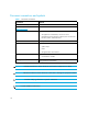
Table 5 Switch factory-default values for reset configuration option (continued) Configuration catagory Description Default Ports Port Names NULL strings Port Blocked States Unblocked FAN Enabled LIN Alerts Enabled Ports enabled 8 Switch addressing IP Address 10.1.1.10 Subnet Mask 255.0.0.0 Gateway Address 0.0.0.0 MAC Address PROM value Operating mode Must select one of two modes: Open Fabric 1.0 or Homogeneous. HP recommends using the Open Fabric 1.0 mode. Open Fabric 1.
Table 5 Switch factory-default values for reset configuration option (continued) Configuration catagory Zoning Description Default Number of Zone Members 0 Number of Zones 0 Number of Zone Sets 0 Zone Names None Zone Sets Names None Zone Members None Default Zone State Disabled Active Zone Set State Disabled Active Zone Set Name NULL string Physical dimensions Table 6 lists Edge Switch 2/24 dimensions. Table 6 Dimensions Dimension Size Height 4.3 cm (1.7 in.) Width 43.4 cm (17.
Table 7 Environmental specifications (continued) Specification Shipping Storage Operating Humidity 5% to 100% 5% to 80% 8% to 80% Maximum wet-bulb 84°F (29°C) temperature 84°F (29°C) 81°F (27°C) Altitude 12,192 m (40,000 ft ) 3,048 m (10,000 ft) 12,192 m (40,000 ft ) Power requirements Table 8 lists Edge Switch 2/24 power requirements.
Laser information Three configurations of cards with fixed optics are provided for each of the connector types: four extended long-wave ports, four long-wave ports, and four short-wave ports.
Technical specifications
Index A access control list configure HAFM Basic 87 description 87 accumulators 104 active zone set state, default value 117 addresses, default values 116 alkaline battery warning 104 asynchronous RS-232 null modem cable 21 audience 9 authentication access control list 87 configure HAFM Basic 87 RADIUS server support 87 settings 87 authentication settings configure HAFM Basic 87 description 87 authorized reseller, HP 11 B backing up switch configuration file 97 batteries recycling or disposal 104 replaceme
port binding 88 HAFM Basic 87 port fencing 87 preferred path 87 RADIUS server HAFM Basic 87 SANtegrity Authentication HAFM Basic 87 SANtegrity Binding HAFM Basic 87 security features HAFM Basic 87 SSL encryption software 83 web 83 switch binding HAFM Basic 87 switch parameters 43 Switch Parameters dialog box 44 zone sets 89 zones 89 zoning (optional) 89 configure menu enable Telnet 65 Configure ports Open Systems management style 49 connectors and indicators 17 conventions document 10 text symbols 10 cord.
switch binding HAFM Basic 87 Telnet 65 Enterprise Fabric Mode configure HAFM Basic 87 description 87 enable HAFM Basic 87 ESD (electrostatic discharge) obtaining additional information 105 precautions 105 prevention measures 105 storing products 105 transporting products 105 types of damage from 105 wrist strap 21 Ethernet events, configure at HAFM appliance 55 events, enable at HAFM appliance 55 hub, unpacking, inspecting, and installing 29 European Union, regulatory compliance notice 102 F F_Port, descri
defined 14 launching 69 HAFM Basic Edition.
NVRAM 43, 46 O online state, setting 41 open fabric 1.
modifications 100 shielded cables 100 related documentation 9 release notes 92 replacing a power cord 104 rerouting delay 45 RFI/EMI connector hoods 100 routing delay, default value 116 S safety ESD grounding cable with wrist strap 21 fiber-optic protective plug 20 SANtegrity Authentication access control list 87 configure HAFM Basic 87 configure PFE key HAFM Basic 85 RADIUS server support 87 settings 87 SANtegrity Binding configure HAFM Basic 87 configure PFE key HAFM Basic 85 Enterprise Fabric Mode confi
rerouting delay 45 setting date and time 38 tools supplied 20 unpacking and inspecting 24 verifying communication to HAFM appliance 37 switch binding configure HAFM Basic 87 description 87 enable HAFM Basic 87 switch firmware adding version 92 deleting a version 95 downloading 95 version 91 switch parameters domain RSCNs 45 insistent domain ID 45 NVRAM storage 43, 46 preferred domain ID 44 rerouting delay 45 suppress RSCNs on zone set activations 45 symbols in text 10 system preventing electrostatic dischar