
edge switch 2/32 product manager user guide


edge switch 2/32 product manager user guide 2–7
Monitoring and Managing the Switch
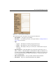
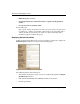
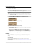
Rear View
1. Power Supply Status — Each AC power connector indicates the location of an
internal power supply. A simulated green LED indicator is located in the upper
left corner of each AC power connector. The indicator illuminates if the power
supply is working and receiving AC power.
When a blinking red and yellow diamond ( ) displays on a power connector, like
in Figure 2–1 on page 2-5, the internal power supply for that connector failed. In
this case, the green indicator to the top left of the connector will not illuminate.
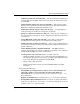
When the green indicator is on and no status symbol displays, the power supply is
operational. Note that the Switch operates with one power supply failure, however
replace the power supply as soon as possible to retain redundancy.
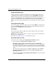
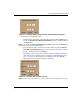
2. Fan Status — Four fan modules are installed in the Edge Switch 2/32 to cool the
power supplies and CTP card. Note that the CTP card is an internal component
and not a FRU.
A simulated amber LED is located in the above left corner of each fan module.
When the LED indicator on a fan module illuminates, as shown in the previous
illustrations, and a blinking red and yellow diamond ( ) displays over a module,
the fan has failed or is rotating insufficiently. You should replace failed fan
modules as soon as possible. Note that the Switch continues to operate with one
fan failure. If two or more fans fail, replace them as soon as possible to avoid
Switch damage.