
edge switch 2/32 product manager user guide

edge switch 2/32 product manager user guide 2–25
Monitoring and Managing the Switch
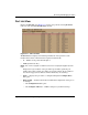
• Position — Slot position of FRU in the chassis relative to identical FRUs also
installed in the chassis.
There are four fan modules (positions 0-3), one CTP card (position 0), two power
supplies (positions 0-1), and 32 port positions (0-31).
• Status — Active or failed. Active displays always unless the FRU fails.
Failed displays if the FRU is not functional.
• Part Number — Part number of the FRU.
• Serial Number — Serial number of the FRU.
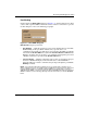
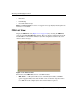
Node List View
Display the Node List view in the view panel by choosing Node List from the view
tabs on the Product Manager window. This view displays information about all node
attachments to any F_Ports on the Switch sorted by port number. All data is dynamic
and updates automatically as devices log in and log out.
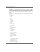
Figure 2–13: Node List View
Information that displays for each node includes:
• Port # — Number of the port, from 0 through 31.
• Address
— In S/390 mode, this displays the logical port address (port number plus 4).
— In Open Systems mode, this displays the node’s Fibre Channel address.