
FW 08.01.00 McDATA® Sphereon 3032 and 3232 Fabric Switches Installation and Service Manual (620-000155-220, November 2005)
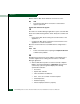
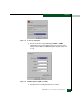
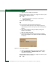
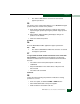
Table Of Contents
- Preface
- General Information
- Installation Tasks
- Factory Defaults
- Installation Options
- Summary of Installation Tasks
- Task 1: Verify Installation Requirements
- Task 2: Unpack, Inspect, and Install the Ethernet Hub (Optional)
- Task 3: Unpack, Inspect, and Install the Switch
- Task 4: Configure Network Information
- Task 5: LAN-Connect the Switch
- Task 6: Unpack, Inspect, and Install the Management Server
- Task 7: Configure Management Server Password and Network Addresses
- Task 8: Configure Management Server Information
- Task 9: Configure Windows 2000 Users
- Task 10: Set Management Server Date and Time
- Task 11: Configure the Call-Home Feature (Optional)
- Task 12: Assign User Names and Passwords
- Task 13: Configure the Switch to the Management Application
- Task 14: Record or Verify Management Server Restore Information
- Task 15: Verify Switch-to-Management Server Communication
- Task 16: Configure PFE Key (Optional)
- Task 17: Configure Management Server (Optional)
- Flexport
- Open Trunking
- Task 18: Set Switch Date and Time
- Task 19: Configure the Sphereon 3032/3232 Element Manager Applications
- Task 20: Configure Switch Operating Parameters
- Task 21: Configure Fabric Operating Parameters
- Fabric Parameters
- Configure Ports (Open Systems Mode)
- Configure Ports (FICON Mode)
- Configure Port Addresses (FICON Mode)
- Configure SNMP Trap Message Recipients
- Configure and Enable E-mail Notification
- Configure and Enable Ethernet Events
- Configure and Enable Call-Home Event Notification
- Configure Threshold Alerts
- Procedures
- Task 22: Configure Open Trunking
- Task 23: Test Remote Notification (Optional)
- Task 24: Back Up Configuration Data
- Task 25: Configure the Switch from the EFCM Basic Interface (Optional)
- Configure Product Identification
- Configure Date and Time
- Configure Parameters
- Configure Fabric Parameters
- Configure Network Information
- Configure Basic Port Information
- Configure Port BB_Credit
- Configure Port NPIV
- Configure SNMP
- Enable CLI
- Enable or Disable Host Control
- Configure SSL Encryption
- Install PFE Keys (Optional)
- Configure Security
- Configure Interswitch Links
- Task 5: Configure Product Network Information (Optional)
- Task 26: Cable Fibre Channel Ports
- Task 27: Connect Switch to a Fabric Director (Optional)
- Task 28: Register with the McDATA File Center
- Diagnostics
- Maintenance Analysis Procedures
- MAP 0000: Start MAP
- MAP 0100: Power Distribution Analysis
- MAP 0200: POST, Reset, or IPL Failure Analysis
- MAP 0300: Console Application Problem Determination
- MAP 0400: Loss of Console Communication
- MAP 0500: Fan and CTP Card Failure Analysis
- MAP 0600: Port Failure and Link Incident Analysis
- MAP 0700: Fabric, ISL, and Segmented Port Problem Determination
- MAP 0800: Server Hardware Problem Determination
- Repair Information
- Factory Defaults
- Procedural Notes
- Using Log Information
- Using Views
- FRU List View
- Performing Port Diagnostics
- Swapping Ports
- Collecting Maintenance Data
- Clean Fiber-Optic Components
- Power-On Procedure
- Power-Off Procedure
- Reset or IPL the Switch
- Set the Switch Online or Offline
- Block and Unblock Ports
- Manage Firmware Versions
- Manage Configuration Data
- Install or Upgrade Software
- FRU Removal and Replacement
- Illustrated Parts Breakdown
- Messages
- Event Code Tables
- Restore EFC Server
- Consolidating EFC Servers in a Multiswitch Fabric
- Glossary
- Index

3
MAP 0400: Loss of Console Communication
3-55
Diagnostics
b. After a few seconds, the LCD panel displays the following
(Figure 3-19):
Figure 3-19 LCD Panel (LAN 2 IP Address)
c. Depending on switch-to-server LAN connectivity, record the
appropriate IP address (LAN 1 or LAN 2).
Continue to the next step.
21
Configure the EFC Server reporting the Duplicate Session
communication problem as a client.
a. At the Product View, select Logout from the Logout/Exit menu on
the navigation control panel. The EFC Manager Login dialog box
displays.
b. At the EFC Manager Login dialog box, type a user name and
password (obtained in MAP 0000: Start MAP on page 3-6).
c. Type the IP address of the EFC Server running the first instance
of the EFC Manager application in the EFC Server field.
d. Click Login. The EFC Manager application opens as a client and
the Product View displays.
Did the EFC Server reconfigure as a client and did the Ethernet
connection recover?
NO YES
↓ The switch-to-EFC Server connection is restored and the
second EFC Server appears operational as a client.
Contact the next level of support.
22
The IP address defining the switch to the EFC Manager application is
incorrect or unknown and must be verified. A maintenance terminal
(desktop or notebook PC) and asynchronous RS-232 modem cable
are required to verify the switch IP address. Both tools are provided
by installation or service personnel. To verify the switch IP address:
LAN 2:
010.001.001.001