
FW 08.01.00 McDATA® Sphereon 3032 and 3232 Fabric Switches Installation and Service Manual (620-000155-220, November 2005)
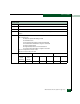
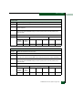
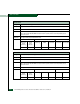
Table Of Contents
- Preface
- General Information
- Installation Tasks
- Factory Defaults
- Installation Options
- Summary of Installation Tasks
- Task 1: Verify Installation Requirements
- Task 2: Unpack, Inspect, and Install the Ethernet Hub (Optional)
- Task 3: Unpack, Inspect, and Install the Switch
- Task 4: Configure Network Information
- Task 5: LAN-Connect the Switch
- Task 6: Unpack, Inspect, and Install the Management Server
- Task 7: Configure Management Server Password and Network Addresses
- Task 8: Configure Management Server Information
- Task 9: Configure Windows 2000 Users
- Task 10: Set Management Server Date and Time
- Task 11: Configure the Call-Home Feature (Optional)
- Task 12: Assign User Names and Passwords
- Task 13: Configure the Switch to the Management Application
- Task 14: Record or Verify Management Server Restore Information
- Task 15: Verify Switch-to-Management Server Communication
- Task 16: Configure PFE Key (Optional)
- Task 17: Configure Management Server (Optional)
- Flexport
- Open Trunking
- Task 18: Set Switch Date and Time
- Task 19: Configure the Sphereon 3032/3232 Element Manager Applications
- Task 20: Configure Switch Operating Parameters
- Task 21: Configure Fabric Operating Parameters
- Fabric Parameters
- Configure Ports (Open Systems Mode)
- Configure Ports (FICON Mode)
- Configure Port Addresses (FICON Mode)
- Configure SNMP Trap Message Recipients
- Configure and Enable E-mail Notification
- Configure and Enable Ethernet Events
- Configure and Enable Call-Home Event Notification
- Configure Threshold Alerts
- Procedures
- Task 22: Configure Open Trunking
- Task 23: Test Remote Notification (Optional)
- Task 24: Back Up Configuration Data
- Task 25: Configure the Switch from the EFCM Basic Interface (Optional)
- Configure Product Identification
- Configure Date and Time
- Configure Parameters
- Configure Fabric Parameters
- Configure Network Information
- Configure Basic Port Information
- Configure Port BB_Credit
- Configure Port NPIV
- Configure SNMP
- Enable CLI
- Enable or Disable Host Control
- Configure SSL Encryption
- Install PFE Keys (Optional)
- Configure Security
- Configure Interswitch Links
- Task 5: Configure Product Network Information (Optional)
- Task 26: Cable Fibre Channel Ports
- Task 27: Connect Switch to a Fabric Director (Optional)
- Task 28: Register with the McDATA File Center
- Diagnostics
- Maintenance Analysis Procedures
- MAP 0000: Start MAP
- MAP 0100: Power Distribution Analysis
- MAP 0200: POST, Reset, or IPL Failure Analysis
- MAP 0300: Console Application Problem Determination
- MAP 0400: Loss of Console Communication
- MAP 0500: Fan and CTP Card Failure Analysis
- MAP 0600: Port Failure and Link Incident Analysis
- MAP 0700: Fabric, ISL, and Segmented Port Problem Determination
- MAP 0800: Server Hardware Problem Determination
- Repair Information
- Factory Defaults
- Procedural Notes
- Using Log Information
- Using Views
- FRU List View
- Performing Port Diagnostics
- Swapping Ports
- Collecting Maintenance Data
- Clean Fiber-Optic Components
- Power-On Procedure
- Power-Off Procedure
- Reset or IPL the Switch
- Set the Switch Online or Offline
- Block and Unblock Ports
- Manage Firmware Versions
- Manage Configuration Data
- Install or Upgrade Software
- FRU Removal and Replacement
- Illustrated Parts Breakdown
- Messages
- Event Code Tables
- Restore EFC Server
- Consolidating EFC Servers in a Multiswitch Fabric
- Glossary
- Index
B
MPC Module Events (600 through 699)
B-71
Event Code Tables
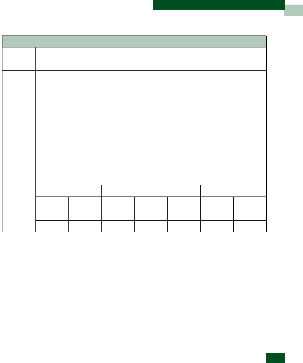
Event Code: 604
Message: SBAR module failure
Severity: Major
Explanation: A failure criteria associated with the serial crossbar hardware module has been met.
Action: Perform the data collection procedure for the switch using the EFC Manager, and return the CD to McDATA for
analysis.
Event Data: Byte 0 = Slot position
Byte 1 = Reason code
00 = Operator requested with debug command
02 = Initialization failure
03 = Hot plug/power up diagnostics failure acknowledgement
04 = Communications with hardware is irregular or non-existent
05 = Read of module ID failed
06 = High availability statistical error threshold reached
07 = Communication with hardware is irregular or non-existent
Bytes 4-7 = Elapsed millisecond tick counter
Bytes 8-11 = Reason code specific data
Distribution: Switch EFC Server Host
Nonvolatile
System
Event Log
System
Error
Indicator
Event Log E-Mail Call-Home Sense Info Link Incident
✔✔✔✔✔✔