
HP StorageWorks Data Replication Manager HSG80 ACS Version 8.7P Configuration Guide (AA-RPHZF-TE, March 2004)


Configuring the Optional Entry-Level DRM Solutions
154 Data Replication Manager HSG80 ACS Version 8.7P Configuration Guide
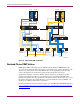
e. Connect a fiber optic cable from port 1 of the top controller of Controller Pair Y to
port 5 of the Fibre Channel switch.
f. Connect a fiber optic cable from port 2 of the top controller of Controller Pair Y to
port 7 of the Fibre Channel switch.
g. Connect a fiber optic cable from port 1 of the bottom controller of Controller Pair Y to
port 15 of the Fibre Channel switch.
h. Connect a fiber optic cable from port 2 of the bottom controller of Controller Pair Y to
port 13 of the Fibre Channel switch.
Note: You should see an illuminated green LED on the switch as soon as each cable is inserted
at both ends. This verifies that there is a good connection.
3. Make the following host connections:
a. Connect a fiber optic cable from HBA A of Host A to port 0 of the Fibre Channel
switch.
b. Connect a fiber optic cable from HBA B of Host A to port 12 of the Fibre Channel
switch.
c. Connect a fiber optic cable from HBA A of Host Y to port 2 of the Fibre Channel
switch.
d. Connect a fiber optic cable from HBA B of Host Y to port 14 of the Fibre Channel
switch.
Note: Because this configuration uses only one switch, there will not be an ISL. This eliminates the
procedure for connecting the external fiber links as described in Chapter 4 in the sections titled
“Connect the Target Site to the External Fiber Link” and “Connect the Initiator Site to the External
Fiber Link.”
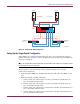
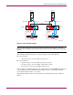
Single-Fabric Configuration
This configuration, illustrated in Figure 24 with 8-port switches, is designed for small,
entry-level tests and proof-of-concept demonstrations where some distance is needed between
the switches in the solution. Larger port count switches are also supported up to the
proportional limits listed for 8-port switches. This non-disaster-tolerant solution can also be
used to produce copies of data needed for data migration or data mining. Fabric zoning, if
desired, is used to create two logical fabrics out of the one physical fabric. For more
information on zoning, refer to your switch documentation.
Because a GBIC is used between switches, and all multimode cables are local to a switch, the
ISL can be any supported transport, like single-mode fiber, dense wavelength division
multiplexing (DWDM), or asynchronous transport mode (ATM). There is no distance
limitation between sites.