
HP StorageWorks Replacing an HSG60 or HSG80 Array Controller Installation Instructions (EK-80CTL-IM. F01, March 2005)

Page 2
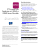
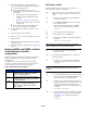
Figure 1: HSG60 or HSG80 array controller with optical GLM
In Figure 1, 9-pin D-sub to 25-pin D-sub adapters are not
shown. Table 1 lists optional adapters that can be used for
terminal connections on HSG60 and HSG80 array controllers.
Part numbers for these adapters are also listed.
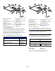
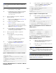
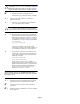
Figure 2: HSG60 or HSG80 array controller with copper GLM
Note: In Figure 2, 9-pin D-sub to 25-pin D-sub adapters are not
shown. See Table 1 for additional information on other optional
adapters that can be used for a terminal connection.
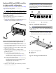
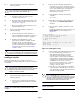
Figure 3 illustrates the array controller and cache module
relationship. Controller A and cache A function together as a
set; controller B and cache B function together as a set.
Figure 3: Controller and cache module bay locations
1 Backplane connector
2 Access door
3 Optical gigabit link module
(GLM)
4 Program card slot
5 Program card Ejection button
6 Program card
7 Program card electrostatic
discharge (ESD) cover
8 Fibre Channel optical host
bus adapter
9 Maintenance port cable for a
PC connection
- Maintenance port
q Operator control panel and
controller LEDs
w Release lever
Table 1: Optional Adapters for a Terminal Connection
Description Part Numbers
Male-to-female (null modem) 173407–001 /
12–45238–01
Male-to-male (null modem) 173407–002 /
12–45238–02
Male-to-male (modem) 173407–003 /
12–45238–03
5033
1 2 3 4 5 6
1
6
4
5
3
2
8
11
9
10
12
7
1 Backplane connector
2 Access door
3 Copper GLM
4 Program card slot
5 Program card Ejection button
6 Program card
7 Program card ESD cover
8 Fibre Channel copper host
bus cables
9 Maintenance port cable for a
PC connection
- Maintenance port
q OCP and controller LEDs
w Release lever
1 Controller A
2 Controller B
3 Cache A
4 Cache B
5034
1 2 3 4 5 6
1
9
4
5
3
2
11
10
12
6
7
8
5032
1
2
3 4