
HSG80 ACS Solution Software V8.6 for Windows NT and Windows 2000 Installation and Configuration Guide


6–2 HSG80 ACS Solution Software Version 8.6 for Windows NT and Windows 2000 Installation and
Configuration Guide
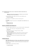
Figure 6–1 shows an example storage system map for the BA370 enclosure. Details on
building your own map are described in Chapter 2. Templates to help you build your
storage map are supplied in Appendix A.
Figure 6–1. Example storage map for the BA370 Enclosure
The figure shows a representative multiple-bus failover configuration. Restricting the
access of unit D101 to host BLUE can be done by enabling only the connections to host
BLUE. At least two connections must be enabled for multiple-bus failover to work. For
most operating systems, it is desirable to have all connections to the host enabled. The
example system, shown in Figure 6–2, contains three non-clustered Windows
NT/Windows 2000 hosts. Port 1 link is separate from port 2 link (that is, ports 1 of both
controllers are on one loop or fabric, and port 2 of both controllers are on another)
therefore, each adapter has two connections.
Port
1234 5 6
Power
Supply
D2
S2
DISK10300
D2
S2
DISK20300
D2
S2
DISK30300
D2
S2
DISK40300
D2
D101
DISK50300
spareset
member
DISK60300
Power
Supply
3
Targets
Power
Supply D0
S1
MI
DISK10200
D0
S1
M1
DISK20200
D0
S1
M2
DISK30200
D0
S1
M2
DISK40200
D1
M3
DISK50200
D1
M3
DISK60200
Power
Supply
2
Power
Supply
D120
R2
DISK10100
D120
R2
DISK20100
D120
R2
DISK30100
D120
R2
DISK40100
D120
R2
DISK50100
D120
R2
DISK60100
Power
Supply
1
Power
Supply
D102
R1
DISK10000
D102
R1
DISK20000
D102
R1
DISK30000
D102
R1
DISK40000
D102
R1
DISK50000
D102
R1
DISK60000
Power
Supply
0