
HSG80 ACS Solution Software V8.6 for Windows NT and Windows 2000 Installation and Configuration Guide


Planning a Subsystem 1–5
Selecting a Failover Mode
Failover is a way to keep the storage array available to the host if one of the controllers
becomes unresponsive. A controller can become unresponsive because of a hardware
failure, such as a controller or, in multiple-bus only, due to a failure of the link between
host and controller or host-bus adapter. Failover keeps the storage array available to the
hosts by allowing the surviving controller to take over total control of the subsystem.
There are two failover modes:
■ Transparent, which is handled by the surviving controller and is invisible
(transparent) to the hosts.
■ Multiple-bus, which is handled by the hosts.
Either mode of failover can work with loop or fabric topology.
Transparent Failover Mode
Transparent failover mode has the following characteristics:
■ Hosts do not know failover has taken place
■ Units are divided between host ports 1 and 2
A unit or storage unit is a physical or virtual device of the subsystem. It is typically
assigned a logical unit number (LUN) and is managed by the HSG80 controller and
presented to a server through the Fibre Channel bus and the server’s host bus adapter.
Disks that are set up as independent disks (JBODs) or RAIDsets are referred to as
storagesets. Storagesets are units.
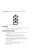
In transparent failover mode, host port 1 of controller A and host port 1 of controller B
must be on the same Fibre Channel link. Host port 2 of controller A and host port 2 of
controller B must also be on the same Fibre Channel link. Depending on operating system
restrictions and requirements, the port 1 link and the port 2 link can be separate links, or
they can be the same link.
At any time, host port 1 is active on only one controller, and host port 2 is active on only
one controller. The other ports are in standby mode. In normal operation, both host port 1
on controller A and host port 2 on controller B are active. A representative configuration is
shown in Figure 1–5. The active and standby ports share port identity, enabling the
standby port to take over for the active one. If one controller fails, its companion controller
(known as the surviving controller) takes control by making both its host ports active, as
shown in Figure 1–6.