
HP StorageWorks ESL E-Series e2400-FC 2Gb Interface Controller Upgrade (AA928-96014, October 2007)


ACT/
LNK
ACT/
LNK
PORT 1 PORT 0 ETHERNET
SERIAL
PWR
FIBRE
CHANNEL
FIBRE
CHANNEL
ACT/
LNK
PORT 2
FIBRE
CHANNEL
ACT/
LNK
ACT/
LNK
PORT 1 PORT 3
FIBRE
CHANNEL
FIBRE
CHANNEL
ACT/
LNK
PORT 2
FIBRE
CHANNEL
ACT/
LNK
ACT/
LNK
PORT 1 PORT 0 ETHERNET
SERIAL
PWR
FIBRE
CHANNEL
FIBRE
CHANNEL
ACT/
LNK
PORT 2
FIBRE
CHANNEL
ACT/
LNK
ACT/
LNK
PORT 1 PORT 0
FIBRE
CHANNEL
FIBRE
CHANNEL
ACT/
LNK
PORT 2
FIBRE
CHANNEL
ACT/
LNK
ACT/
LNK
PORT 1 PORT 0 ETHERNET
SERIAL
PWR
FIBRE
CHANNEL
FIBRE
CHANNEL
ACT/
LNK
PORT 2
FIBRE
CHANNEL
ACT/
LNK
ACT/
LNK
PORT 1 PORT 3
FIBRE
CHANNEL
FIBRE
CHANNEL
ACT/
LNK
PORT 2
FIBRE
CHANNEL
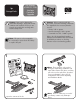
9
Connect each FC cable to the appropriately
labeled TD port on the interface controller. Once
connected, insert the FC cable bundle into the
cable clip to the right of the card cage.
Using a #2 Phillips screwdriver, remove the screw
from the clamp located on the lower right side
of the drive cluster. Route the FC cable bundle
through the clamp, then secure the clamp to
the cluster frame by replacing the screw.
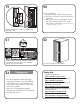
FC Cable Configuration
8
FC cables are labeled near their connectors to
indicate which TD port to connect to each port on
the interface controller. Plan to first connect the
FC cables to the interface controller, then route
them through the cabinet, and finally, connect
them to the drive.
Drive TD Port
A0
B1
C2
D3
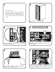
10
Route the cable through the
cable access holes in the sheet
metal on the right of the library
cabinet.
For drive clusters 0 through 2,
dip the excess cable length
down into the upper cable
access hole. For drive clusters 3
through 5, route the cables up through the lower
and upper access holes. Push the first set of cables
to the back of the library to create space for
additional cables. This will help prevent the cables
from becoming tangled.
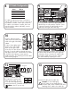
11
FC Port A
FC Port B
Remove FC port A end caps
from the drive if present and
attach the FC cable. Be sure
to use the cable appropriately
labeled for the drive, identified as A, B, C, or D.
Note: Use FC port A only.
12
FC Port A
FC Port B
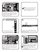
13
Insert the FC cable into the cable clip.
Caution: To avoid damaging
the FC cable, do not sharply bend or
pinch the cable. Allow a radial bend when
attaching the FC cable to the cable clip.
B A
D C