HP StorageWorks ESL E-Series Tape Library Unpacking and Installation Guide This guide provides information to help you: • • • • Unpack the library Install the library Load tape cartridges Configure the library *350800-011* Part number: 350800-011 11th edition: March 2010
Legal and notice information © Copyright 2004, 2010 Hewlett-Packard Development Company, L.P. The information contained herein is subject to change without notice. The only warranties for HP products and services are set forth in the express warranty statements accompanying such products and services. Nothing herein should be construed as constituting an additional warranty. HP shall not be liable for technical or editorial errors or omissions contained herein.
Contents 1 Unpacking the library ......................................................................... 9 Selecting an installation location ................................................................................................... 9 Floor space ....................................................................................................................... 10 Floor clearance ..................................................................................................................
5 Support and other resources .............................................................. 65 Contacting HP .......................................................................................................................... Subscription service ............................................................................................................ New and changed information in this edition ............................................................................... Related information .....
Figures 1 Floor space requirements (standalone libraries) ........................................................... 10 2 Floor space requirements (CLM libraries) .................................................................... 11 3 Power supply cable ................................................................................................. 12 4 Wall outlet (NEMA L6-20R rated 250VAC 20 amps) ...................................................
33 Attaching an Ultrium bar code label .......................................................................... 46 34 Proper Ultrium bar code label placement ................................................................... 46 35 SDLT cartridge ........................................................................................................ 47 36 Write-protecting Ultrium tape cartridges .....................................................................
Tables 1 Media label identifiers ............................................................................................. 48 2 Ultrium library storage elements (removable magazines) .............................................. 55 3 Ultrium library storage elements (fixed magazines) ...................................................... 56 4 SDLT library storage elements (removable magazines) .................................................. 57 5 SDLT library storage elements (fixed magazines) ......
1 Unpacking the library This chapter contains the following sections: • • • • • “Selecting an installation location” on page 9 “Preparing for the installation” on page 13 “Unpacking the library” on page 14 “Setting up the library” on page 23 “Storing the packaging materials” on page 32 CAUTION: Only qualified HP field service engineers should unpack the HP StorageWorks ESL E-Series tape library.
Floor space Figure 1 on page 10 shows the minimum floor space required for a standalone library. 1. 28 inches (71 cm) 2. 30 inches (76 cm) 3. Back door 4. 50 inches (127 cm) 5. Front door 6. 23 inches (58 cm) Figure 1 Floor space requirements (standalone libraries) .
Minimum floor space for CLM libraries is shown in Figure 2. 1. Back door clearance—28 inches (71 cm) 2. Depth of cabinets—50 inches (127 cm) 3. Front door clearance—23 inches (58 cm) 4. Width of cabinets—30 inches (76 cm) per CLM library cabinet 5. Space between cabinets—1 inch (2.5 cm) 6. Clearance left of primary cabinet—52 inches (130 cm) used during installing and servicing the CLM library Figure 2 Floor space requirements (CLM libraries) . Floor clearance The library has a floor clearance of 0.
Power and grounding For the United States and Canada, one or two UL/CSA-certified power cables are supplied with each library. Each power cable uses a 14/3 SJT cord, a L6-20P plug, and an IEC-C320 C19 female connector (see Figure 3). 1. Connect to wall outlet plug NEMA L6–20P 2. Connects to library power supply connector IECC320 C19 Figure 3 Power supply cable . The library is rated 200-240V~, 50-60Hz.
NOTE: More information on the electrical requirements is provided in the HP StorageWorks ESL E-Series Pre-Installation Site Survey. WARNING! To avoid damage to the library and risk to personal safety, the library must be connected to a grounded electrical outlet.
Taking ESD precautions CAUTION: Some components within the library contain static-sensitive parts. To avoid damaging these parts while performing installation procedures, always observe the following precautions. • Keep the library powered off during all installation procedures. • Keep the library power cable plugged into a grounded power outlet, except when working with AC electrical components.
Unpacking the library To unpack the library: 1. Note the side of the pallet where the library will be unloaded. The library may be unloaded from only the ramp side of the pallet (see Figure 5). 2. Verify the minimum floor space requirements (see Figure 5 on page 15). NOTE: Figure 5 shows the minimum floor space required by the library at its unboxing site. Unboxing the library requires a minimum of 3 feet (91 cm) on all sides. The side used for the unloading ramp requires 14 feet (4.26 m).
3. Cut the two poly bands and stretch film that secure the library and packing material to the pallet (see Figure 6). WARNING! The poly bands are under tension and may snap away when cut. Wear safety goggles when cutting the poly bands. 1. Poly bands Figure 6 Removing the steel bands .
4. Lift the cardboard box top cover straight up and remove it from the box (see Figure 7). Figure 7 Removing the box top cover .
5. Unwrap the two pieces of the corrugated paperboard box from the library (see Figure 8). Figure 8 Removing the cardboard box . 6. Remove the cardboard cornerposts from each corner of the library. They are secured with plastic sheeting (see Figure 9). Figure 9 Removing the cornerposts .
7. Cut the tape securing the ramps against the library. WARNING! Be sure to hold the ramps against the library when cutting the tape to prevent the ramps from falling. 8. Remove the accessory kit from the pallet (located on the side opposite the ramp). Set it aside for later use at the installation site. 9. Remove the ramps from the pallet and cut the stretch tape that secures the ramp supports and cardboard. Set the cardboard to the side with the accessory box (see Figure 10).
10. Place the ramps on the pallet. There are guide holes on the ramp side of the pallet (see Figure 11). NOTE: Make sure that the ramp supports are square with the floor as shown. Figure 11 Attaching the ramp to the pallet .
11. Using a 3/4-inch socket, remove the four restraining bolts securing the library to the shipping pallet (see Figure 12). One restraining bolt is located near each leveling foot on the library. 1. Bolts Figure 12 Removing the restraining bolt .
12. Raise the leveling feet securing the library to the pallet (see Figure 13). 1. Leveling feet in raised position Figure 13 Raising the leveling feet . Moving the library to the installation site WARNING! Libraries weigh between 1,135 pounds (515 kg) and 1,459 pounds (662 kg), depending on their configuration. At least two people should move and install the library. 1. 22 Map a route to the installation site.
2. Carefully roll the library down the ramp and guide it to the installation site (see Figure 14). Figure 14 Rolling the library down the ramp . Setting up the library 1. Stabilize the library by lowering the leveling feet: 2. a. Rotate each foot of the library until it makes contact with the floor. b. Rotate each foot an additional 1/4 turn to begin raising the library. c. Level the library using a carpenter's level. Remove the antistatic bag covering the library. 3.
6. From the front of the library, remove the foam from the Y-axis cover plate and from the left front door. From the back of the library, remove the foam from the back door frame (see Figure 15). Store the foam in case you need to relocate the library in the future. 1. Foam on back of library Figure 15 Removing the shipping foam . 24 Unpacking the library 2.
7. Remove the internal library frame restraint from the front of the library, by completing these steps (see Figure 16). a. b. c. Remove the four 1/4-inch hex nuts securing the two pieces of the restraint together. Remove the two hex head bolts securing the restraint to the top and bottom of the library frame. Collapse the internal library frame restraints and store them inside the back doors on each side. Mounting studs are provided to secure the restraints.
8. From the front of the library, remove two shipping restraints using a #2 Phillips screwdriver (see Figure 17). The vertical axis shipping restraint is secured by four screws, and the robot shipping restraint is secured by seven screws. 1. Robot shipping restraint 2. Vertical axis shipping restraint Figure 17 Removing the vertical axis and robot shipping restraints .
9. Attach the vertical axis shipping restraint to the robot shipping restraint using the four screws removed from the vertical axis shipping restraint in Figure 17 (see Figure 18). 1. Shipping restraints in storage position 2. Spare screws 3. Shipping restraints Figure 18 Storing the vertical axis and robot shipping restraints . 10. Store the five spare screws in the robot shipping restraint as shown in Figure 18. 11.
12. From the back of the library use a ratchet with a 7/16-inch socket or a 7/16-inch open-end wrench to remove the two nuts securing the counterweight shipping restraint to the back wall of the library cabinet (see Figure 19). NOTE: HP recommends that you use a 12-inch socket extension. 1. Counterweight shipping restraint 2. Nuts Figure 19 Removing the counterweight shipping restraint .
13. Reverse the counterweight shipping restraint so that the pin is facing out. Reinstall it onto the back wall of the library using the two nuts previously removed (see Figure 20). 1. Counterweight shipping restraint with retaining pin facing out 2. Nuts Figure 20 Storing the counter weight shipping restraint . 14. Remove the six panel shipping restraints—three on each side of the cabinet. a. The load ports are located in the center bin panel on each side of the library.
b. Pull out the load port to expose the middle and lower shipping restraints (see Figure 22). 1. Upper shipping restraint 2. Middle shipping restraint 3. Lower shipping restraint 4. Load port latching mechanism Figure 22 Removing the panel shipping restraints . c. d. e. f. 30 Using a #2 Phillips screwdriver, remove the middle and lower panel shipping restraints. Close the load port.
15. Store the panel shipping restraint hardware (three sets on each side) on the lower cabinet frame (see Figure 23). 1. Panel restraint storage location (left side shown) Figure 23 Storing the panel shipping restraints . 16. Using the power cables from the accessory kit, connect the library to a grounded power source, using the following procedure. a. b. c. Route the cables up through the cable access hole at the bottom of the cabinet. Connect the cables to the library power distribution unit.
Storing the packaging materials Store the library packaging materials: 1. Detach the ramp and place it on top of the pallet. 2. Fold the shipping bag. 3. Place the shipping bag, foam cap, bolts, and other packaging materials on the pallet. 4. Collapse the cardboard box. 5. Place the cardboard box on top of the packaging materials on the pallet. 6. Secure the packaging materials to the pallet and store for future use.
2 Installing the library NOTE: For configure-to-order libraries, kits ship with power cables appropriate to the region instead of US standard power cables.
Cabling the library The following sections include procedures for cabling the library. These procedures will be slightly different for the e2400-160 interface controller and Ultrium 460 drives, the e2400-FC 2Gb and 4Gb interface controller and Ultrium 460-FC and 960 drives, and the e2400-FC 2Gb interface controller and Ultrium 1840 and 3280 drives. The instructions for cabling each type of library are presented below.
NOTE: A step stool may be needed to reach the e2400-160 interface controllers in the card cage located at the top of the library cabinet. 1. Attach a SCSI terminator (provided) to the top SCSI port on each Ultrium 460 or SDLT drive (see Figure 24). 1. Terminators Figure 24 Attaching SCSI terminators to the Ultrium 460 or SDLT drive . 2. Remove the top screw from the cable restraint bracket and loosen the bottom one to prepare for cable routing (see Figure 25).
3. Connect the SCSI cables from the drives in drive cluster 0 to the e2400-160 interface controller in slot 0 of the card cage (see Figure 26). 1. Port 0 2. Port 1 3. Port 2 4. Port 3 A. Drive A B. Drive B C. Drive C D. Drive D Figure 26 Matching drives and interface controller ports . NOTE: Drive SCSI cables are labeled “A”, ”B”, ”C”, and ”D” on the drive end to indicate the drive location.
CAUTION: Do not overtighten the screws that secure the cable to the drive port. b. Route each cable through the cable access holes in the sheet metal on the right of the library cabinet. For drive clusters 0 through 2, dip the excess cable length down into the upper cable access hole. For drive clusters 3 through 5, route the cables up through the lower and upper access holes. Push the first set of cables to the back of the library to create space for additional cables.
c. Continue routing the cable up through the cable restraint bracket located to the right of the card cage and attach the cable to the corresponding SCSI port on the e2400-160 interface controller. NOTE: Tighten the SCSI connector screw on the left and then the right for easier installation due to cable interference. Pull the cable toward you to provide more clearance when tightening the right connector screw. d. e. 38 Repeat these steps until all SCSI drives are connected.
4. The e2400-160 interface controller ships with several sets of tie wraps. Each color set should be used to designate a different drive cluster (see Figure 28). 1. Color tie wrap 2. White tie wrap 3. Matching color tie wrap Figure 28 Attaching the tie wraps . NOTE: Make sure that different colors of tie wraps are used for each drive cluster and e2400-160 interface controller combination. If you have multiple sets of the same color, do not use them within the same library.
NOTE: The other white tie wraps are provided as spares. 5. Route the SCSI cables through the cluster cable clamp on the lower right corner of the cluster frame (see Figure 29). Figure 29 Routing cables through the cluster cable clamp . 6. a. Using a #2 Phillips screwdriver, remove the screw from the clamp. b. Route the SCSI cables through the clamp. c. Secure the clamp to the cluster frame by replacing the screw.
3. Connect the FC cables to a switch or an HBA. NOTE: You can connect directly to an HBA or to a switch. The default is to connect to a switch. For detailed procedures for connecting to an HBA, please see HP StorageWorks Interface Manager and Command View TL User Guide. Figure 30 Connecting FC cables for LTO3 or earlier tape drives .
2. Attach the cable to the front Ethernet port on the cabinet controller located at the base of the library. The ports are on the right side toward the back of the cabinet controller (see Figure 31). 1. Ethernet ports Figure 31 Connecting the cabinet controller LAN cable .
Powering on the library You are now ready to power on the library and make sure that all components are functioning properly (see Figure 32). 1. Front door latch 2. Power button Figure 32 Powering on the library . NOTE: Normally, all library doors should be closed before powering on the library; however, to confirm that all components are functioning properly after the initial installation, leave the back library door open. 1.
Installing the library
3 Loading tape cartridges Before configuring the library you need to load the appropriate tape cartridges. For information about tape cartridges needed for each tape drive type, please see HP StorageWorks Tape Libraries Media and Bar Code Labels flyer. This chapter includes the following sections: • “Preparing tape cartridges” on page 45 • “Library storage locations and slot numbering” on page 50 NOTE: Tape cartridges and cleaning cartridges must be ordered specifically.
labels on your tape cartridges. Your host software may keep track of the following information and the associated bar code: • • • • • Date of format or initialization Media pool of the tape Data residing on the tape Age of the backup Errors encountered while using the tape (to determine if the tape is faulty) Ultrium bar code labels Ultrium cartridges have a recessed area located on the face of the cartridge next to the write-protect switch.
SDLT bar code labels SDLT cartridges have a front slide slot located on the face of the cartridge next to the write-protect switch (see Figure 35). Use this slot for inserting the bar code label by sliding it into the slot. CAUTION: Do not apply labels onto the top, bottom, sides, or back of the cartridge as this may cause damage to the tape drive, or interfere with reliable operation. 1. Barcode label 2. Orange indicator 3. Write protect—slide left 4. Write enabled—slide right 5.
Media label identifiers Be sure to use the proper bar code labels for your drive technology. Table 1 lists the identifier that is found at the end of 7- or 8-character SDLT and Ultrium bar code labels. Table 1 Media label identifiers Cartridge type Density Label identifier SDLT 110/220 GB S or S1 SDLT 160/320 GB S or S2 SDLT 600 300/600 GB 2 Ultrium 230 100/200 GB L1 Ultrium 460 200/400 GB L2 Ultrium 960 400/800 GB L3 LT (WORM) Ultrium 1840 800 GB/1.
Setting the write-protect switch Each tape cartridge has a sliding write-protect switch. This switch determines whether new data can be written to the tape cartridge (write-enabled) or whether data on the tape cartridge is protected from being erased or overwritten (write-protected). Write-protecting Ultrium tape cartridges By moving the switch to the left (Figure 36), the tape cartridge is write-enabled. By moving the switch to the right, the tape cartridge is write-protected. 1. Write-enabled 2.
Write-protecting SDLT tape cartridges By moving the switch to the left (Figure 37), the tape cartridge is write-protected (orange indicator is visible). By moving the switch to the right, the tape cartridge is write-enabled (orange indicator is not visible). 1. Barcode label 2. Orange indicator 3. Write protect—slide left 4. Write enabled—slide right 5. Insertion arrow Figure 37 Write-protecting SDLT tape cartridges .
To slide the slot panels out of the cabinet, press the slot panel latches down and pull the slot panel out of the cabinet (see Figure 38). Figure 38 Releasing the slot panel latch .
Figure 39 shows the left panel bins. Begin with panel 1 and load top to bottom and left to right. Continue with panel 2 in the same manner, and finally, panel 3. 1. Panel 1 3. Panel 3 Figure 39 Bin shelf numbering, left panels . 52 Loading tape cartridges 2.
Figure 40 shows the right panel bins. Begin with panel 4 and load top to bottom and left to right. Continue with panel 5 in the same manner, and finally, panel 6. 1. Panel 4 2. Panel 5 3. Panel 6 Figure 40 Bin shelf numbering, right panels .
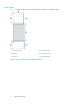
Figure 41 shows the back panel bins. With Ultrium drives, each column has seven slots; with SDLT drives, each column has six slots. Begin at the top, with the panel corresponding to cluster 0, and load top to bottom and left to right. Continue loading each sequential cluster, top to bottom and left to right. NOTE: The number of slots located in the back panel varies with the number of drive clusters installed. 1. Cluster 0 Figure 41 Back panel bins (SDLT shown) . 54 Loading tape cartridges 2.
Ultrium library Table 2 shows storage capacity in Ultrium-only libraries with removable magazines.
Table 3 shows storage capacity in Ultrium-only libraries with fixed magazines.
SDLT library Table 4 shows storage capacity in an SDLT-only library with removable magazines.
Table 5 shows storage capacity in an SDLT-only library with fixed magazines.
per partition. See HP StorageWorks Interface Manager and Command View TL User Guide to learn about and use library partitioning. Removable magazines are also required in a mixed-media library. These requirements impact library operations in the following ways: • If you convert panel 1 only to a new media type, neither load port can be used to insert or remove media from that panel. Because the left and right load ports are on panels 2 and 5, they must have the same media type as the rest of panels 2 and 5.
Loading tape cartridges
4 Configuring the library 1. Make sure the library is powered on. If it is not: a. b. On the front of the library, push the power button to turn on the library (the button will depress). The library will take 20 minutes or more to boot, depending on the configuration. Verify that the current state of the library that appears on the OCP is “Online, OK”. 1. Front door latch 2. Power button Figure 42 Powering on the library . 2. Take the library off-line, if it is not off-line already. a. b. c.
3. Press Menu from the Home screen. The OCP displays the Menu screen (see Figure 43). Figure 43 Menu screen . 4. From the Menu screen, use the Up and Down buttons to highlight Setup and press Select. 5. The library prompts you for a password. Enter the 6 digit password. NOTE: The default password is 001122. The Setup screen displays (see Figure 44). Figure 44 Setup screen .
The Setup screen displays the following information: • • • • • • • • • • • • 6. Change Network Settings Change Password Restore Factory Settings Lock Element Addressing (used on Cross Linked systems with 3 or more cabinets) Quick Loadport Open Drive Autoclean Drive Autounload Barcode Length Configured Drives Both Load Ports Left Load Port (##) Right Load Port (##) Load port slot numbers will be different for each drive technology (Ultrium is 16 and 32, and SDLT is 14 and 28).
• To enable or disable autounload, use the Up and Down buttons to select Autounload and press Select, then use the Up and Down buttons to choose Enable or Disable, then press Select. • To set the barcode length, use the Up and Down buttons to select Barcode Length and press Select. To set the barcode length, use the Up and Down buttons to display the appropriate number (from 1 to 9, or back to 0), then press Select. Default barcode length is 0, which means that a barcode of any length is accepted.
5 Support and other resources Contacting HP For worldwide technical support information, see the HP support website: http://www.hp.
HP websites For additional information, see the following HP websites: • • • • • • http://www.hp.com http://www.hp.com/go/storage http://www.hp.com/service_locator http://www.hp.com/support/manuals http://www.hp.com/support/downloads http://www.hp.com/storage/whitepapers Typographic conventions Table 6 Document conventions Convention Element Blue text: Table 6 Cross-reference links and e-mail addresses Blue, underlined text: http://www.hp.
IMPORTANT: Provides clarifying information or specific instructions. NOTE: Provides additional information. Rack stability Rack stability protects personnel and equipment. WARNING! To reduce the risk of personal injury or damage to equipment: • • • • • Extend leveling jacks to the floor. Ensure that the full weight of the rack rests on the leveling jacks. Install stabilizing feet on the rack. In multiple-rack installations, fasten racks together securely. Extend only one rack component at a time.
Support and other resources
Index A accessory kit, 23 autoclean, 63 B back panel, 50 bar code labels SDLT, Ultrium, bar code, 46 bar code labels Ultrium, 46 barcode length, bolts, restraining, 21 both load ports, bracket, cable restraint, C cable clamp, cable restraint bracket, cables FC, 40, 41 I2C, 34 managing, 37 power, 31 SCSI, 34, 36 capacity, storage, cartridge slots, 50 configured drives, configuring IP address, configuring the library, 61 contacting HP, 65 conventions document, 66 text symbols, 66 Cross Link (CLM), 33 custom
installing drive cluster cables, I2C cable, 34 IP address, configuring, 61 L LAN cable, 41 left load port, left panel, leveling feet, leveling feet, 22, 23 library partitioning, 58 load port, 58 load slots, 50 loading tapes, M magazines, removable, 58 media label identifiers, 48 menu, 62 mixed media, 58 Model 630e, 57, 58, 59 Model 712e, 55, 56 N network settings, O OCP, 62 P panel back, 50 left, 50 right, 50 slots, 50 partitioning, 58 password, 62, 63 ports FC interface controller, power cables, 31 co
websites customer self repair, 67 HP , HP Subscriber's Choice for Business, 65 product manuals, 65 write-protecting SDLT tapes, 50 Ultrium tapes, 49 HP StorageWorks ESL E-Series Tape Library 71