
HP StorageWorks ESL E-Series Tape Library Unpacking and Installation Guide (350800-011, May 2010)


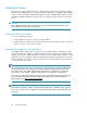

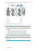
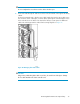

Table Of Contents
- HP StorageWorks ESL E-Series Tape Library
- 1 Unpacking the library
- 2 Installing the library
- 3 Loading tape cartridges
- 4 Configuring the library
- 5 Support and other resources
- Index
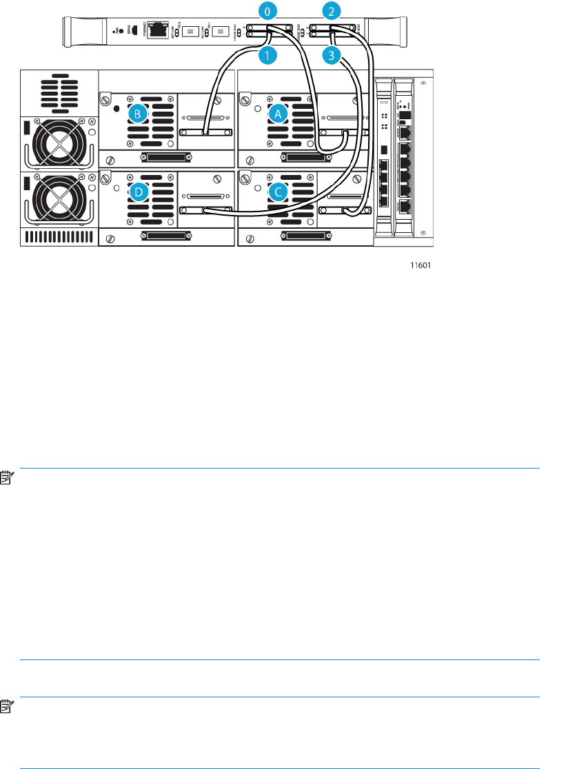
3. Connect the SCSI cables from the drives in drive cluster 0 to the e2400-160 interface controller
in slot 0 of the card cage (see Figure 26).
2. Port 11. Port 0
4. Port 33. Port 2
B. Drive BA. Drive A
D. Drive DC. Drive C
Figure 26 Matching drives and interface controller ports
.
NOTE:
Drive SCSI cables are labeled “A”, ”B”, ”C”, and ”D” on the drive end to indicate the drive
location. Drive SCSI cables are labeled ”0”, ”1”, ”2”, and ”3” on the interface controller
end to indicate the SCSI port location. The most efficient order for making these connections
is as follows:
1. Connect a SCSI cable from drive A to port 0 on the interface controller.
2. Connect a SCSI cable from drive B to port 1 on the interface controller.
3. Connect a SCSI cable from drive C to port 2 on the interface controller.
4. Connect a SCSI cable from drive D to port 3 on the interface controller.
NOTE:
Clusters are numbered sequentially from 0 to 5, with 0 at the top of the cabinet, just below
the card cage.
a. Gently tighten the screws to secure the cable to the drive port using a slotted screwdriver.
Installing the library36