
HP StorageWorks ESL E-Series Tape Library Cluster Upgrade Instructions (February 2004)
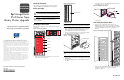
Note: I
2
C cables are labeled “PO” through “P5” and correspond to
the drive clusters. Ensure you use the appropriate cable for the drive
cluster being installed (that is cable “P1” for drive cluster “1”).
Figure 6: Connecting the I
2
C cable
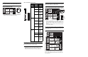
3. Review Table 1 before connecting the drive cluster Ethernet
cables. How you connect these cables will depend on how
many drive clusters are installed in the library.
Note: Depending on which drive cluster you are installing, some of
the following steps may have already been completed during a
previous installation. If you are adding drive cluster 1, some cables on
drive cluster 0 will need to be moved or removed.
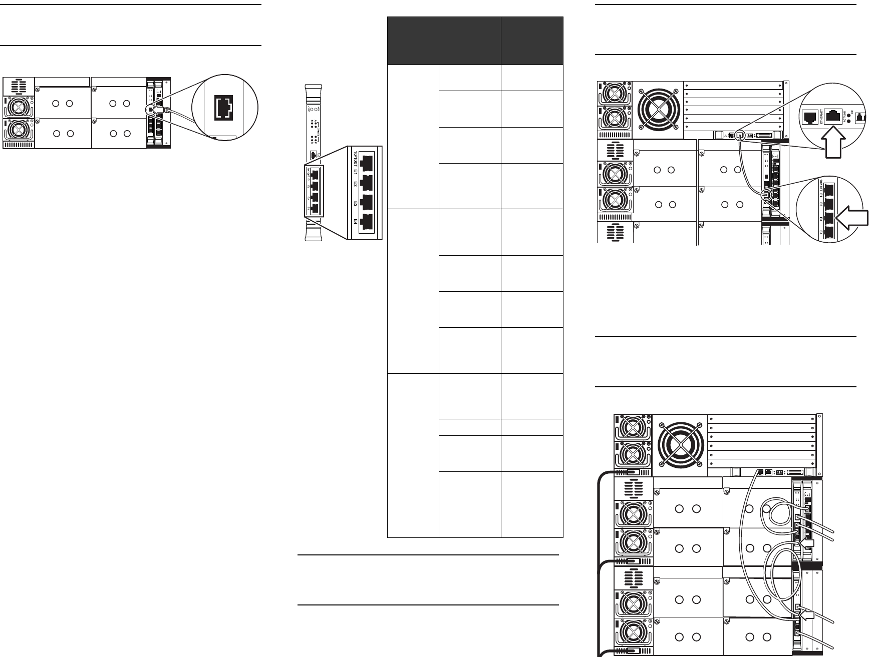
4. If adding drive cluster 1, connect the 3 ft green Ethernet cable
from Ethernet port “E2” on the cluster controller to the
Ethernet port on the robotics controller card (e1200-160)
located in the bottom slot of the card cage (see Figure 7).
Note: If you are installing drive cluster 1, you will need to remove the
cable from drive cluster 0’s controller card at port “E4” and connect it
to port “E3” on drive cluster 1’s cluster controller card. A daisy-chain
Ethernet cable will replace it as outlined in step 5.
Figure 7: Connecting the Ethernet cable to the robotics controller
5. Add a 1 ft gray Ethernet cable from Ethernet port “E4” on the
cluster controller in the upper drive cluster to Ethernet port
“E1” on the cluster controller in the drive cluster below it (see
Figure 8).
Continue daisy-chaining until you have done this procedure
for all the drive clusters.
Note: When daisy-chaining drive clusters, do so from Ethernet port
“E4” on the top cluster to Ethernet port “E1” on the cluster below. This
will help keep the cables clear from the other Ethernet cables on the
cluster controller card.
Figure 8: Daisy-chaining drive clusters
Installing tape drives
The new drive cluster is now ready for tape drive installation.
Proceed to the installation instructions that came with the tape
drive upgrade kit.
I2C
Table 1: Cluster Ethernet cable connections
Drive
cluster
Cluster
controller
Ethernet
port
Ethernet
cable
0E1 Cabinet
controller
E2 Interface
Manager
card
E3 e2400-160
interface
controller
E4 Daisy-chain
to lower
cluster
controller
1E1 Daisy-chain
to upper
cluster
controller
E2 e1200-160
robotics
controller
E3 e2400-160
interface
controller
E4 Daisy-chain
to lower
cluster
controller
2
through
5
E1 Daisy-chain
to upper
cluster
controller
E2 Not used
E3 e2400-160
interface
controller
E4 Daisy-chain
to lower
controller
(not used
for cluster
5)