
HP 30-10022-01 Loop Switch User Guide (5697-5674, May 2006)


8 Switch Installation
Ethernet LEDs
The Ethernet LEDs indicate the network connection status:
System LEDs
The System LEDs indicate the switch’s status, independent of the port LEDs.
FAULT
POWER
TEMP
10101
1
2
3
4
5
6
7
8
9101112
100-240 V~, 50/60 H
Z
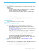
Figure 1 Switch View Depicting Ethernet, Port, and System LEDs
Port LED
Ethernet LEDs
System LEDs
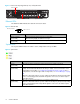
Ethernet LEDs Indication
Ethernet Activity
(green LED)
• When flashing, the Ethernet port is receiving data.
• When flashing rapidly, the traffic level is high.
Ethernet Link
(green LED)
When lit, the switch is connected to an operational Ethernet.
Figure 2 Ethernet LEDs
Ethernet Activity
Ethernet Link
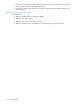
System LEDs Indication
Power
(green LED)
When lit, the switch is plugged in and the internal power supply is functional.
Fault
(yellow LED)
When lit, an event has occurred that meets or exceeds the current Fault LED threshold
setting. The default Fault LED threshold setting is “critical”. For more information on the
Fault LED threshold setting, see “Setting the Fault LED Threshold” on page 24.
For a
complete list of event messages and severity levels, see
: Event Messages on page
45
.
Note: The switch will continue to operate. Switch functionality may be impaired depending
on the event that triggered the Fault LED. Regardless of the cause, the switch requires
immediate attention.
Temp
(yellow LED)
When lit, the internal temperature has exceeded acceptable levels.
Note: The switch will continue to operate. Switch functionality may be impaired depending
on the event that triggered the Temp LED. Regardless of the cause, the switch requires
immediate attention.
Figure 3 System LEDs