installation and reference guide hp surestore fc 1Gb/2Gb entry switch 8B and fc 1Gb/2Gb switch 8B www.hp.
Notice Safety notices © Hewlett-Packard Company, 2001. All rights reserved. Any servicing, adjustment, maintenance, or repair must be performed only by authorized service-trained personnel. Edition: E1201 Hewlett-Packard Company makes no warranty of any kind with regard to this material, including, but not limited to, the implied warranties of merchantability and fitness for a particular purpose.
Contents Preface Chapter 1 Chapter 2 About This Guide . . . . . . . . . . . . . . . . . . . . . . . . . . . . . . . . . . . . . . . . . . v Related Publications . . . . . . . . . . . . . . . . . . . . . . . . . . . . . . . . . . . . . . . . v Getting Help . . . . . . . . . . . . . . . . . . . . . . . . . . . . . . . . . . . . . . . . . . . . . . vi Getting Software Updates. . . . . . . . . . . . . . . . . . . . . . . . . . . . . . . . . . . . vi Introducing the Switch Overview . . . . . . . . .
Chapter 3 Operating the Switch Turning the Switch On and Off. . . . . . . . . . . . . . . . . . . . . . . . . . . . . . . . 3-1 Interpreting LED Activity. . . . . . . . . . . . . . . . . . . . . . . . . . . . . . . . . . . . 3-1 LEDs on the SFP Media Side . . . . . . . . . . . . . . . . . . . . . . . 3-2 LEDs on the Fan Side . . . . . . . . . . . . . . . . . . . . . . . . . . . . . . 3-4 Interpreting POST Results . . . . . . . . . . . . . . . . . . . . . . . . . . . . . . . . . . .
Preface About This Guide This guide provides the following information about the HP Surestore FC 1Gb/2Gb Entry Switch 8B and FC 1Gb/2Gb Switch 8B: Chapter 1 Introducing the Switch Overview information about the switch. Chapter 2 Installing and Configuring the Switch Instructions for installing and configuring the switch. Chapter 3 Operating the Switch Instructions for operating the switch and interpreting system activity.
Title Part Number Web Tools User’s Guide, version 3.0 Available on CD Distributed Fabrics User’s Guide, version 3.0 Available on CD Zoning User’s Guide, version 3.0 Available on CD MIB Reference Manual, version 3.0 Available on CD ISL Trunking User’s Guide, version 3.0 Available on CD Advanced Performance Monitoring User’s Guide, version 3.
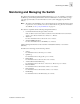
Chapter Introducing the Switch 1 This chapter provides the following information: • • Overview on page 1-1 Monitoring and Managing the Switch on page 1-3 Overview The FC Entry Switch 8B and FC Switch 8B are eight-port Fibre Channel fabric switches that support link speeds up to 2 Gbps. Both switches include Fabric OS version 3.0.1b or later, and are compatible with the entire HP installed base of Fibre Channel hubs, bridges, and switches.
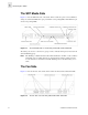
1 Introducing the Switch The SFP Media Side Figure 1-1 shows the SFP media side of the switch, which contains the power connector, IP label, serial port, switch status LED, fiber optic ports and their corresponding LEDs, and the Ethernet port and its corresponding LEDs. Figure 1-1 The SFP Media Side of the FC Entry Switch 8B and FC Switch 8B The switch ports are color-coded into two groups of four, to indicate which ports can be used in the same ISL Trunking group.
Introducing the Switch 1 Monitoring and Managing the Switch The switch can be managed in-band using Fibre Channel protocol, or out-of-band by connecting to the Ethernet port. The management functions allow the administrator to monitor fabric topology, port status, physical status, and other information to aid in system debugging and performance analysis.
1 1-4 Introducing the Switch Installation and Reference Guide
Chapter Installing and Configuring the Switch 2 The FC Entry Switch 8B or FC Switch 8B can be installed as a stand-alone unit or in a rack that meets EIA (Electronic Industries Association) standards.
2 Installing and Configuring the Switch Package Contents The major items included in the shipping carton(s) include the following items: • • • • • • • • One FC Entry Switch 8B or FC Switch 8B One 10 ft. RS-232 serial cable (convertible to an RJ-45 connector by removing the adapter on the end of the cable) One grounded 6 ft.
Installing and Configuring the Switch 4. 2 Provide power to the switch by connecting the power cord to the switch power supply and to a power outlet. Ensure the power cord is routed so that it is not exposed to stress. Power is supplied to the switch as soon as the cord is connected. The switch runs POST (power on self-test) by default each time it is turned on. Note: Do not connect the switch to the network until the IP address is correctly set.
2 Installing and Configuring the Switch (8) #8 Flat washer (6) M5 Torx head screw with captive lock washer (2) Rubber washer (4) M5 U-type Tinnerman clip (HP rack only) (4) #10-32 square Tinnerman nut (Compaq/Rittal rack only) (4) #10-32 x 5/8 Phillips pan-head screw with attached lock washer (Compaq/Rittal rack only) (6) Spacer (Compaq/Rittal rack only) (4) M5 flat washer (Compaq/Rittal rack only) CAUTION For proper airflow, the SFP media side of the FC Entry Switch 8B or FC Switch 8B faces the r
Installing and Configuring the Switch 2 To install the switch in an HP rack: 1. Check contents of the shipping carton to verify all the required parts and hardware are available. 2. Choose a mounting location in the rack for the switch. 3. Attach the rear rail-tray brackets to the rear rack uprights by installing each of the two mounting brackets with one M5 Torx head screw with captive lock washer as shown in Figure 2-2.
2 Installing and Configuring the Switch 4. Install two M5 U-type Tinnerman clips for each of the front columns of the rack in the top and bottom positions of the three-hole EIA pattern as shown in Figure 2-3.
Installing and Configuring the Switch 5. 2 Assemble the outer rails by completing the following steps: a. As an aid in assembly, two rubber washers have been included to help keep the rear slotted portion of the outer rail flush against the rear rail-tray brackets. Install them as shown in Figure 2-4. Figure 2-4 b. Installation and Reference Guide Installing the Rubber Washers Insert the alignment pins attached to the outer rail front flange into the center opening in the rack.
2 Installing and Configuring the Switch c. Note: Install one M5 Torx screw in the upper hole location of the right rail. Then, install one M5 Torx screw in the lower location of the left rail. See Figure 2-5. Do not install the upper left and lower right screws until later. Figure 2-5 6.
Installing and Configuring the Switch 7. Insert the switch with the attached inner rails into the outer rails as shown in Figure 2-7. Figure 2-7 8. 2 Installing the Switch into an HP Rack Install the two remaining M5 Torx screws into the upper left and lower right holes to complete the installation. See Figure 2-8.
2 Installing and Configuring the Switch 9. Provide power to the switch by connecting the power cord to the switch power supply and to a power outlet. Ensure the power cord is routed so that it is not exposed to stress. Power is supplied to the switch as soon as the cord is connected. The switch runs POST (power on self-test) by default each time it is turned on. Note: Do not connect the switch to the network until the IP address is correctly set.
Installing and Configuring the Switch 4. 2 Install two #10-32 square Tinnerman nuts for each of the front columns of the rack in the top and bottom positions of the three-hole EIA pattern. Also install one spacer in the center position for each column on the front of the rack. See Figure 2-10.
2 Installing and Configuring the Switch 5. Assemble the outer rails by completing the following steps: a. As an aid in assembly, two rubber washers have been included to help keep the rear slotted portion of the outer rail flush against the rear rail-tray brackets. Install them as shown in Figure 2-11. Figure 2-11 Installing the Rubber Washers b. Note: 2-12 Insert the alignment pins attached to the outer rail front flange into the center opening in the rack.
Installing and Configuring the Switch c. Note: 2 Install one #10-32 x 5/8 Phillips pan-head screw in the upper hole location of the right rail. Then, install one #10-32 x 5/8 Phillips pan-head screw in the lower location of the left rail as shown in Figure 2-12. Do not install the upper left and lower right screws until later.
2 Installing and Configuring the Switch 6. Assemble each of the two inner rails (one on each side of the switch and plenum) using eight #8-32 x 5/16 Phillips pan-head screws (with attached star lock washers) and eight #8 flat washers as shown in Figure 2-13. CAUTION Do not use any other screws other than the eight that are provided. Use of any longer lengths can cause damage to internal components of the switch. Be sure to install the flat washers along with the pan-head screws.
Installing and Configuring the Switch 8. 2 Install the remaining #10-32 x 5/8 Phillips pan-head screws into the upper left and lower right holes to complete the installation. See Figure 2-15. Figure 2-15 Securing the Switch 9. Provide power to the switch by connecting the power cord to the switch power supply and to a power outlet. Ensure the power cord is routed so that it is not exposed to stress. Power is supplied to the switch as soon as the cord is connected.
2 Installing and Configuring the Switch Configuring and Connecting the Switch This procedure provides instructions for configuring and connecting the FC Entry Switch 8B or FC Switch 8B for use in a network and fabric.
Installing and Configuring the Switch g. Enter the following at the terminal emulator application prompt: ipAddrSet. h. Enter the requested information at the prompts: • • • • • • Optional: Verify the address was correctly set by entering the following: ipAddrShow. j. Record the IP address on the label provided for this purpose on the switch. k. Once the IP address is verified as correct, remove the serial cable and replace the shipping plug in the serial port.
2 Installing and Configuring the Switch 5. 6. a. Disable the switch by entering the following: switchDisable. b. Then enter the following to display the configuration prompts: configure. c. Enter “y” after the prompt “Fabric parameters”. For example: Fabric parameters (yes, y, no, n): [no] y d. Enter a unique domain ID: Domain: (1..239) [1] 3. e. Complete the remaining prompts or press CTRL+D to accept the remaining settings without completing all the prompts. f.
Installing and Configuring the Switch 2 Saving the System Configuration Files Upload the switch configuration file for disaster recovery and keep it in a safe place where it can be easily found. Backing up the configuration after the initial configuration changes and periodically thereafter is strongly recommended. Backing up the Switch Configuration Settings FTP must be used on Windows workstations to backup the system configuration. The FTP server must be running before an upload can occur.
2 Installing and Configuring the Switch Restoring the System Configuration Settings To restore the system configuration settings from a backup: 1. Verify that the RSHD service or the FTP service is running on the host workstation (Windows or UNIX). 2. Log on to the switch as the admin user. 3. Shut down the switch by entering the following command: switchDisable. 4.
Installing and Configuring the Switch 2 Setting Up Speed Negotiation There are two methods for configuring the ports on the FC Entry Switch 8B and FC Switch 8B. The port can be set to auto-sensing mode, which allows the port to automatically be configured to the highest speed. Ports can also be set to a fixed speed of either 1 or 2 Gbps. To display the configuration settings of the ports on a switch, use the portCfgShow.
2 Installing and Configuring the Switch HP Surestore VA 7400 The FC Entry Switch 8B or FC Switch 8B also can support a 2 Gb connection to an HP Surestore Virtual Array 7400. Set the port speed to 2 Gb using the telnet command portCfgSpeed. Use the Virtual Front Panel (VFP) on the VA 7400 and configure the device as follows: 1. Change the controller port data rate to 2 Gbps. a. To change the port data rate to 2 Gbps for controller 1, enter: vfpmgr -S 2 -c 1. When prompted to reset, enter no. b.
Chapter Operating the Switch 3 This chapter provides the following information: • • • • Turning the Switch On and Off on page 3-1 Interpreting LED Activity on page 3-1 Interpreting POST Results on page 3-4 Maintaining the Switch on page 3-5 Turning the Switch On and Off To turn the FC Entry Switch 8B or FC Switch 8B on, connect the power cable to the power connector on the switch and to a power source. The switch takes approximately 4.5 minutes to boot after it is turned on.
3 Operating the Switch LEDs on the SFP Media Side Figure 3-1 shows the SFP media side of the switch with the LEDs identified. Figure 3-1 Note: The SFP Media Side of the FC Entry Switch 8B and FC Switch 8B The LEDs may flash different colors during diagnostic tests and POST. This does not indicate a problem unless the LEDs do not display a healthy pattern after POST or the other diagnostic tests are complete.
Operating the Switch 3 The following table describes the port status LEDs located above each port on the left. Color of LED Status of Hardware Recommended Action No light No light or signal carrier (media or cable) is detected. Verify that media and cable are both firmly seated and functional. Steady green Port is online (connected to an external No action required. device) but has no traffic.
3 Operating the Switch LEDs on the Fan Side Figure 3-2 shows the fan side of the switch with the LED identified. Figure 3-2 Note: The Fan Side of the FC Entry Switch 8B and FC Switch 8B The LEDs may flash different colors during diagnostic tests and POST. This does not indicate a problem unless the LEDs do not display a healthy pattern after POST or the other diagnostic tests are complete. The following table describes the switch status LED on the fan side of the switch.
Operating the Switch 3 To determine whether POST completed without errors, verify that all LEDs return to a normal state after POST is complete. If one or more LEDs do not return to a normal state, and this is not due to the switch being set to beacon, see Interpreting LED Activity on page 3-1 (for more information about beaconing, refer to the Fabric OS Procedures Guide). Note: If the switch prompt does not display when POST completes, trying pressing ENTER.
3 3-6 Operating the Switch Installation and Reference Guide
Appendix Product Specifications A This appendix provides the following information: • • • • • • • • • • • Switch Components on page A-1 Weight and Physical Dimensions on page A-2 Facility Requirements on page A-2 Power Supply Specifications on page A-3 Environmental Requirements on page A-3 General Specifications on page A-3 Memory Specifications on page A-5 Optical Port Specifications on page A-5 Serial Port Specifications on page A-5 POST Specifications on page A-6 Regulatory Compliance on page A-7
A Product Specifications • • • Five fans: - Two dedicated to cooling the power supply, three dedicated to cooling the motherboard. - Air is pulled in through the rear intake and pushed out through the vents in the SFP media side. Three digital thermometers, capable of sensing a temperature range from -55°C to +125°C, in 0.5°C increments. A real-time clock (RTC) with a 10-year battery and 56 bytes of NVRAM.
Product Specifications A Power Supply Specifications The power supply is universal and capable of functioning worldwide without using voltage jumpers or switches. It meets IEC 61000-4-5 surge voltage requirements and is autoranging in terms of accommodating input voltages and line frequencies. The power supply specifications for the FC Entry Switch 8B and FC Switch 8B are listed in the following table.
A Product Specifications The general specifications for the FC Entry Switch 8B and FC Switch 8B are listed in the following table.
Product Specifications Specification Description Immunity IEC 61000-4-2 Severity Level 3 for Electrostatic Discharge IEC 61000-4-3 Severity Level 3 for Radiated Fields IEC 61000-4-4 Severity Level 3 for Fast Transients IEC 61000-4-5 Severity Level 3 for Surge Voltage IEC 61000-4-6 Conducted Emissions IEC 61000-4-11 Voltage Variations A Memory Specifications The FC Entry Switch 8B and FC Switch 8B have the following memory: • • • Main memory (SDRAM): 32 MB Flash memory: Dual 8 MB Boot flash: 512K byt
A Product Specifications The port requires a straight serial cable with a female 9-pin subminiature-D connector. Only pins 2, 3, and 5 are supported; if pin 7 is used, the signal must always be driven high, using the pinouts listed in the following table. The cabling pinouts required if pin 7 is used are listed in the following table.
Product Specifications A Regulatory Compliance FCC EMC Statement (USA) This equipment has been tested and found to comply with the limits for a Class A digital device, pursuant to Part 15 of the FCC Rules. These limits are designed to provide reasonable protection against harmful interference when the equipment is operated in a commercial environment.
A Product Specifications VCCI EMC Statement (Japan) Harmonics Conformance (Japan) BSMI EMC Statement (Taiwan) RRL EMC Statement (Korea) Laser Safety A. Certification and Classification Information When equipped with native Fibre Channel adapters, this product contains a laser internal to the small form factor pluggable (SFP) transceiver modules.
Product Specifications A Outside the USA, the SFP is certified as a Class 1 Laser product conforming to requirements contained in IEC 825-1:1993 and EN60825-1:1994, including Amendment 11:1996. The SFP includes the following certifications: • • • • UL Recognized Component (USA) CSA Certified Component (Canada) TUV Certified Component (European Union) CB Certificate (Worldwide) The following figure shows the Class 1 information label that appears on the metal housing of the SFP.
A Product Specifications Declaration of Conformity DECLARATION OF CONFORMITY according to ISO/IEC Guide 22 and EN 45014 Manufacturer's Name: Hewlett-Packard Company Network Storage Solutions Organization Manufacturer's Address: 8000 Foothills Blvd.
Glossary 8b/10b Encoding An encoding scheme that converts each 8-bit byte into 10 bits. Used to balance ones and zeros in high-speed transports. Address Identifier A 24-bit or 8-bit value used to identify the source or destination of a frame. Advanced Performance Monitoring A software product that provides error and performance information to the administrator and end user for use in storage management.
BER Bit Error Rate; the rate at which bits are expected to be received in error. Expressed as the ratio of error bits to total bits transmitted. See also Error. Block As applies to Fibre Channel, upper-level application data that is transferred in a single sequence. Broadcast The transmission of data from a single source to all devices in the fabric, regardless of zoning. See also Multicast, Unicast.
Disparity The relationship of ones and zeros in an encoded character. “Neutral disparity” means an equal number of each, “positive disparity” means a majority of ones, and “negative disparity” means a majority of zeros. Distributed Fabrics The combined user’s guides for the software products Extended Fabrics and Remote Switch. “Distributed Fabrics” is not a software product. See also Extended Fabrics, Remote Switch. DLS Dynamic Load Sharing; dynamic distribution of traffic over available paths.
Fabric Manager A software product that works in conjunction with Web Tools to provide a graphical user interface for managing switch groups as a single unit, instead of as separate switches. Fabric Manager is installed on and run from a computer workstation. Fabric Name The unique identifier assigned to a fabric and communicated during login and port discovery. Fabric OS Operating system on HP Brocade switches.
FSPF Fabric Shortest Path First. Routing protocol for Fibre Channel switches. Full-duplex A mode of communication that allows the same port to simultaneously transmit and receive frames. See also Half-duplex. Fx_Port A fabric port that can operate as either an F_Port or FL_Port. See also F_Port, FL_Port. G_Port Generic Port; a port that can operate as either an E_Port or F_Port. A port is defined as a G_Port when it is not yet connected or has not yet assumed a specific function in the fabric.
JBOD Just a Bunch Of Disks; indicates a number of disks connected in a single chassis to one or more controllers. See also RAID. K28.5 A special 10-bit character used to indicate the beginning of a transmission word that performs Fibre Channel control and signaling functions. The first seven bits of the character are the comma pattern. See also Comma. L_Port Loop Port; a node port (NL_Port) or fabric port (FL_Port) that has arbitrated loop capabilities.
Multimode A fiber optic cabling specification that allows up to 500 meters between devices. N_Port Node Port; a port on a node that can connect to a Fibre Channel port or to another N_Port in a point-to-point connection. See also NL_Port, Nx_Port. Name Server Frequently used to indicate Simple Name Server. See also SNS. NL_Port Node Loop Port; a node port that has arbitrated loop capabilities. Used to connect an equipment port to the fabric in a loop configuration through an FL_Port.
Private Device A device that supports arbitrated loop protocol and can interpret 8-bit addresses, but cannot log into the fabric. Private Loop An arbitrated loop that does not include a participating FL_Port. Protocol A defined method and a set of standards for communication. Public NL_Port An NL_Port that logs into the fabric, can function within either a public or a private loop, and can communicate with either private or public NL_Ports.
SI Sequence Initiative. Single Mode The fiber optic cabling standard that corresponds to distances of up to 10 km between devices. SNMP Simple Network Management Protocol. An internet management protocol that uses either IP for network-level functions and UDP for transport-level functions, or TCP/IP for both. Can be made available over other protocols, such as UDP/IP, because it does not rely on the underlying communication protocols. See also Community (SNMP).
U_Port Universal Port; a switch port that can operate as a G_Port, E_Port, F_Port, or FL_Port. A port is defined as a U_Port when it is not connected or has not yet assumed a specific function in the fabric. UDP User Datagram Protocol; a protocol that runs on top of IP and provides port multiplexing for upper-level protocols. ULP Upper-level Protocol; the protocol that runs on top of Fibre Channel. Typical upper-level protocols are SCSI, IP, HIPPI, and IPI.
Index A E applications supported 1-3 EIA rack requirements A-2 environmental requirements A-3 B bandwidth, aggregate buffers, frame F A-4 A-4 fan side description of LED 3-4 FC-IP A-4 C class Fibre Channel classes supported color-coded ports 1-2 command line, managing by Fibre Channel Association A-4 configuring domain ID 2-17 IP address 2-16 status policies 2-18 switch 2-16 terminal emulator application Fibre Channel classes, supported A-4 frame buffers A-4 I immunity, electromagnetic A-
LEDs colors 3-1 during diagnostic tests 3-1, 3-2, during POST 3-1, 3-2, 3-4 interpreting 3-1 on fan side 3-4 on SFP media side 3-2 port speed LEDs 3-1 port status LEDs 3-1 3-4 POST duration 3-1, A-6 error messages 3-4, A-6 interpreting 3-4 LED indicators 3-1, 3-2, specifications A-6 power supply general information A-1 specifications A-3 protocol, ANSI A-4 3-4 M 3-5 management interfaces 1-3 maintenance, switch monitoring compatible interfaces 1-3 through LED activity 3-1 R rack requirements A-2 range
supportShow telnet command switch components A-1 maintenance 3-5 physical dimensions specifications A-1 weight A-2 vi A-2 T technical support vi telnet managing by 1-3 telnet commands supportShow command vi temperature, requirements A-3 terminal emulator application, configuring 2-16 3-5 A-2 tests, diagnostic thermometers transmission range, data A-4 trunking about 1-2 cabling requirements 2-18 U updates, software vi W Web Tools, managing by weight, switch 1-3 A-2 Installation and Reference
Index-4 Installation and Reference Guide