hp StorageWorks fca2355 dual channel PCI host bus adapter installation guide Part Number: AA-RTJWA-TE First Edition (November 2002) This guide describes how to install, configure, and use the diagnostic utilities for the HP StorageWorks FCA2355 dual channel PCI host bus adapter.
©© Hewlett-Packard Company, 2002. All rights reserved. Hewlett-Packard Company makes no warranty of any kind with regard to this material, including, but not limited to, the implied warranties of merchantability and fitness for a particular purpose. Hewlett-Packard shall not be liable for errors contained herein or for incidental or consequential damages in connection with the furnishing, performance, or use of this material. This document contains proprietary information, which is protected by copyright.
Contents About this Guide Intended Audience . . . . . . . . . . . . . . . . . . . . . . . . . . . . . . . . . . . . . . . . . . . . . . . . . . . . . . vii Related Documentation . . . . . . . . . . . . . . . . . . . . . . . . . . . . . . . . . . . . . . . . . . . . . . . . . . vii Document Conventions . . . . . . . . . . . . . . . . . . . . . . . . . . . . . . . . . . . . . . . . . . . . . . . . . . vii Symbols in Text . . . . . . . . . . . . . . . . . . . . . . . . . . . . . . . . . . . . . . . . . . . . .
Contents Installing the HBA into a Computer. . . . . . . . . . . . . . . . . . . . . . . . . . . . . . . . . . . . . . . . 2–2 Verifying the Installation . . . . . . . . . . . . . . . . . . . . . . . . . . . . . . . . . . . . . . . . . . . . . . . . 2–3 Configuration Guidelines . . . . . . . . . . . . . . . . . . . . . . . . . . . . . . . . . . . . . . . . . . . . . . . . 2–3 3 Installing the SCSI Miniport Driver Introduction. . . . . . . . . . . . . . . . . . . . . . . . . . . . . . . . . . . . . . . . .
Contents Show Host Bus Adapter Info. . . . . . . . . . . . . . . . . . . . . . . . . . . . . . . . . . . . . . . . . 5–12 Quit the LightPulse Utility/NT Utility. . . . . . . . . . . . . . . . . . . . . . . . . . . . . . . . . . 5–12 A Regulatory Compliance Notices FCC Compliance Information Statement. . . . . . . . . . . . . . . . . . . . . . . . . . . . . . . . . . . . A–1 Japanese Notice . . . . . . . . . . . . . . . . . . . . . . . . . . . . . . . . . . . . . . . . . . . . . . . . . . . .
About this Guide This user guide provides information to help you: • Install, configure, and use the diagnostic utilities for the FCA2355 host bus adapter (HBA) for Windows platforms.
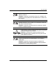
About this Guide Table 1: Document Conventions (Continued) Element Convention User input, command names, system responses (output and messages) Monospace font Variables Monospace, italic font Website addresses Sans serif font (http://thenew.hp.com.) COMMAND NAMES are uppercase unless they are case sensitive Symbols in Text These symbols may be found in the text of this guide. They have the following meanings.
About this Guide Any RJ-45 receptacle marked with these symbols indicates a network interface connection. WARNING: To reduce the risk of electrical shock, fire, or damage to the equipment, do not plug telephone or telecommunications connectors into this receptacle. Any surface or area of the equipment marked with these symbols indicates the presence of a hot surface or hot component. Contact with this surface could result in injury.
About this Guide Rack Stability WARNING: To reduce the risk of personal injury or damage to the equipment, be sure that: • The leveling jacks are extended to the floor. • The full weight of the rack rests on the leveling jacks. • In single rack installations, the stabilizing feet are attached to the rack. • In multiple rack installations, the racks are coupled. • Only one rack component is extended at any time. A rack may become unstable if more than one rack component is extended for any reason.
About this Guide HP Website The HP website has the latest information on this product, as well as the latest drivers. Access storage at: http://thenew.hp.com/country/us/eng/prodserv/storage.html. From this website, select the appropriate product or solution. HP Authorized Reseller For the name of your nearest HP Authorized Reseller: • In the United States, call 1-800-345-1518 • In Canada, call 1-800-263-5868 • Elsewhere, see the HP website for locations and telephone numbers: http://thenew.hp.com.
1 Introduction Overview This introduction to the FCA2355 Host Bus Adapter (HBA) includes: • Product Description • Performance Specifications • Boot BIOS Specifications • Standards • Agency Approvals • Operational Requirements Product Description The FCA2355 Dual Channel PCI host bus adapter offers two independent 2Gbytes/sec Fibre Channel HBA interfaces in a single PCI slot.
Introduction Figure 1–1: FCA2355 Host Bus Adapter Table 1–1: FCA2355 Host Bus Adapter Diagram Description Figure Legend Description Fibre Channel (LC) connectors. POST LEDs indicators Note: See Table 2–1 and Table 4–1 for detailed descriptions. Performance Specifications The FCA2355 is a high-performance I/O solution for applications such as client/server configurations, database I/O environments, multimedia applications, and imaging technologies.
Introduction The FCA2355 is both ANSI Fibre Channel and PCI Local Bus Compliant and supports: • Simultaneous full duplex 2 Gbytes/sec Fibre Channels deliver up to 400MBytes/sec • Automatic speed negotiation • Full fabric support using F_Port and FL_Port connections • Onboard hardware context cache for superior fabric performance • Support for concurrent use of multiple concurrent protocols (SCSI and IP) • Full support for both FC service class 2 and 3 • Support for FC-Tape (FCP-2) devices •
Introduction Boot BIOS System Requirements • Intel Pentium Class computer, with system BIOS copyright 1995 or later • MS-DOS 6.0 or higher • Windows NT 4.0 or Windows 2000 installation media • Installed HBA • Media containing the SCSI Miniport driver • DOS Diagnostic utility, X86DNLD Enabling Boot BIOS and External Boot All HBAs have the BIOS firmware installed as a factory default. However, the BIOS functionality is not enabled.
Introduction Standards The HBA conforms to the following standards: • ANSI Fibre Channel FC-FS • ANSI Fibre Channel FC-PH/PI • ANSI Fibre Channel FC-AL • ANSI Fibre Channel FC-PLDA • ANSI Fibre Channel FC-FLA • PCI Local Bus Revision 2.2 • Fibre Channel Class 2, 3 • PHP Hot plug - Hot swap • SW-2 switch standard Agency Approvals The HBA has the following agency approvals: • Class 1 Laser Product per DHHS 21CFR (J) & EN60825 • UL recognized to UL1950 • CUR recognized to CSA22.2, No.
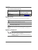
Introduction Operational Requirements The following power, media, and environmental conditions are required for proper HBA operation. Voltage and PCI Slot Requirements Table 1–2 describes the Voltage and minimum PCI slot requirements for the FCA2355 and previously released HP HBAs for Windows platforms. NOTE: Refer to your HP Proliant server PCI slot specifications to determine whether your server and the HBA are compatible.
2 Installation Installation Overview This chapter provides step-by-step instructions for installing the FCA2355 Host Bus Adapter (HBA) including: • Hardware Requirements • Recording Reference Numbers • Installing the HBA into a Computer This chapter also provides information on installation guidelines and supported configurations for the operating systems. IMPORTANT: The HBA contains static-sensitive components. Comply with Electrostatic Discharge (ESD) procedures.
Installation Record the addresses on the lines below for future reference. First IEEE address: __________________________________________________ First Serial number: __________________________________________________ Second IEEE address: __________________________________________________ Second Serial number: __________________________________________________ Installing the HBA into a Computer Following is the procedure for installing the HBA into a computer.
Installation Verifying the Installation To verify the HBA is properly installed and is operating: 1. Turn on the computer. 2. At power up, observe the POST LED indicators on the HBA. The position of the POST LED indicators is defined in Figure 1–1 and Table 1–1 of this guide. The green LED indicates power functions and the amber LED signifies port activity. The amber LED blinks at all times during normal operation. Table 2–1 lists normal LED indications.
3 Installing the SCSI Miniport Driver Introduction This chapter contains step-by-step instructions for installing the Windows NT and Windows 2000 SCSI Miniport drivers. System managers must be familiar with the operating system under which the PCI-to-Fibre Channel Host Bus Adapter (HBA) is to operate. System managers must also have access to standard system documentation. The software kit that is included with the HBA contains the latest version of the HBA’s files and drivers at the time of shipment.
Installing the SCSI Miniport Driver Installing the Windows NT SCSI Miniport Driver Use the following procedure to installing the SCSI device driver and registry parameters for the first time. From the Windows NT desktop: 1. Click Start > Settings > Control Panel. 2. Double click the SCSI Adapters icon. 3. Select the Drivers tab. 4. Click Add. 5. Click Have Disk and select the location of the HBA kit. 6. Select the Fibre Channel SCSI driver and then click OK. 7.
Installing the SCSI Miniport Driver Windows 2000 Device Driver Installation Windows 2000 System Requirements Ensure that your system meets these minimum requirements: • Installed HBA • Windows 2000 Miniport driver and registry parameter file from the software kit provided with the HBA • Windows 2000 Service Pack 2 (recommended) • StorageWorks Fibre Channel Storage subsystem (interconnect device and storage device) Installing the Windows 2000 SCSI Miniport Driver This section contains the steps for
Installing the SCSI Miniport Driver 12. Click Yes to restart Windows 2000. 13. Verify the device driver installation: a. Click Start > Settings > Control Panel. b. Double click the System icon. c. Click Device Manager. d. Verify that the SCSI Miniport driver is present and started. Removing the Windows 2000 SCSI Device Driver To remove the device driver from the Windows 2000 desktop: 1. Click Start > Settings > Control Panel. 2. Double click the System icon. 3. Click Device Manager. 4.
4 Troubleshooting Introduction The Power-On Self Test (POST) and the Windows Event Viewer are troubleshooting utilities you can use for the FCA2355 Host Bus Adapter (HBA). This chapter explains the use of these utilities in the event of an HBA problem. POST Conditions and Results Table 4–1 lists the HBA LED states with descriptions of each.The position of the POST LED indicators is defined in Figure 1–1 and Table 1–1 of this guide. If the LEDs indicate a failure during POST: 1.
Troubleshooting Using The Event Viewer The Windows NT and Windows 2000 SCSI driver verifies the condition of the HBA POST. If there is a failure or a suspected failure, an error log entry is issued to the Windows Event log. Following is the procedure for viewing the event log. From the Main menu: 3. Double click or select the Administrative Tools program group. 4. Double click or select the Event Viewer.
Troubleshooting Table 4–2 describes the SCSI port error log codes Table 4–2: SCSI Port Error Log Codes 0x10 Offset 0xC0 Explanation 0x11 to 0x13 Further Information Invalid Link Speed Selection (Windows NT) 0xD0 SNS_REQ (XMIT_SEQ failed) 0x11 = cmdstat, 12 = parm err 0xD1 SNS_RSP (RCV_SEQ failed) 0x11 = cmdstat, 12 = parm err 0xD3 RCV_ELS_REQ failed 0x11 = cmdstat, 12 = parm err 0xD4 XMT_ELS_REQ failed 0x11 = cmdstat, 12 = parm err 0xD5 Too many targets found (160+) 0x11 to 13 = D_DID tha
Troubleshooting Table 4–2: SCSI Port Error Log Codes (Continued) 0x10 Offset Explanation 0x11 to 0x13 Further Information 0xEC Uncached extension alloc.
Troubleshooting Table 4–3: CmdStat Values 0x11 Offset Explanation Further Information 0x1 IOSTAT_FCP_RSP_ERR 0x2 IOSTAT_REMOTE_STOP Remote sent an ABTS 0x3 IOSTAT_LOCAL_REJECT Parameter field contains additional information 0x4 IOSTAT_NPORT_RJT 0x5 IOSTAT_FABRIC_RJT 0x6 IOSTAT_NPORT_BSY 0x7 IOSTAT_FBRIC_BSY 0x8 IOSTAT_INTERMED_RSP 0x9 IOSTAT_LS_RJT 0xA IOSTAT_BA_RJT Table 4–4: Parameter Error Values Valid only when CmdStat=0x3 Explanation 0x12 Offset 0x00 IOERR_SUCCESS 0x01 IOE
Troubleshooting Table 4–4: Parameter Error Values Valid only when CmdStat=0x3 (Continued) 0x12 Offset 4–6 Explanation (Continued) 0x0D IOERR_TX_DMA_FAILED 0x0E IOERR_RX_DMA_FAILED 0x0F IOERR_ILLEGAL_FRAME 0x10 IOERR_EXTRA_DATA 0x11 IOERR_NO_RESOURCES 0x12 IOERR_RESERVED 0x13 IOERR_ILLEGAL_LENGTH 0x14 IOERR_UNSUPPORTED_FEATURE 0x15 IOERR_ABORT_IN_PROGRESS 0x16 IOERR_ABORT_REQUESTED 0x17 IOERR_RECEIVE_BUFFER_TIMEOUT 0x18 IOERR_LOOP_OPEN_FAILURE 0x19 IOERR_RING_RESET 0x1A IOERR_L
Troubleshooting Table 4–4: Parameter Error Values Valid only when CmdStat=0x3 (Continued) 0x12 Offset Explanation (Continued) 0x22 IOERR_RESERVED 0x23 IOERR_RESERVED 0x24 IOERR_RESERVED 0x25 IOERR_ABORT_MULTI_REQUESTED 0x26 IOERR_RESERVED 0x27 IOERR_RESERVED 0x28 IOERR_LINK_BUFFER_SHORTAGE 0x29 IOERR_RCV_XRIBUF_WAITING SCSI Address Mapping The driver emulates six SCSI buses per HBA to map all 126 possible AL_PA to Target IDs.
Troubleshooting Private Loop Device Mapping In a private loop environment (FC-AL, no switch), devices are initially created based on a fixed address ordering. Once created (at boot), the devices continue to be tracked based on: –WWPN:HardAddress=0;MapNodeName=0 –NodeName:HardAddress=0;MapNodeName=1 –D_ID:HardAddress=1; (MapNodeName=don’t care) This section identifies the initial fixed mapping between the Windows NT bus/target/lun and a Fibre Channel native address (AL_PA/SEL_ID).
Troubleshooting Table 4–5: Current Private Loop Device Mapping (Continued) Bus # 0 Target# 0-31 Lun# 0-7 *AL_PA None SEL_ID None **AL_PA None SEL_ID None 10 0-7 0x1E 0x73 0xD5 0x0A 11 0-7 0x1F 0x72 0xD4 0x0B 12 0-7 0x23 0x71 0xD3 0x0C 13 0-7 0x25 0x70 0xD2 0x0D 14 0-7 0x26 0x6F 0xD1 0x0E 15 0-7 0x27 0x6E 0xCE 0x0F 16 0-7 0x29 0x6D 0xCD 0x10 17 0-7 0x2A 0x6C 0xCC 0x11 18 0-7 0x2B 0x6B 0xCB 0x12 19 0-7 0x2C 0x6A 0xCA 0x13 20 0-7 0x2D 0x69
Troubleshooting Table 4–5: Current Private Loop Device Mapping (Continued) Bus # 0 IMPORTANT: *** Target# 0-31 Lun# 0-7 *AL_PA None SEL_ID None **AL_PA None SEL_ID None 0 0-7 0x43 0x5E 0xB3 0x1F 1 0-7 0x45 0x5D 0xB2 0x20 2 0-7 0x46 0x5C 0xB1 0x21 3 0-7 0x47 0x5B 0xAE 0x22 4 0-7 0x49 0x5A 0xAD 0x23 5 0-7 0x4A 0x59 0xAC 0x24 6 0-7 0x4B 0x58 0xAB 0x25 7 0-7 0x4C 0x57 0xAA 0x26 8 0-7 0x4D 0x56 0xA9 0x27 9 0-7 0x4E 0x55 0xA7 0x28 10 0-7 0x51
Troubleshooting Table 4–5: Current Private Loop Device Mapping (Continued) Bus # 0 IMPORTANT: *** Target# 0-31 Lun# 0-7 *AL_PA None SEL_ID None **AL_PA None SEL_ID None 22 0-7 0x67 0x48 0x84 0x35 23 0-7 0x69 0x47 0x82 0x36 24 0-7 0x6A 0x46 0x81 0x37 25 0-7 0x6B 0x45 0x80 0x38 26 0-7 0x6C 0x44 0x7C 0x39 27 0-7 0x6D 0x43 0x7A 0x3A 28 0-7 0x6E 0x42 0x79 0x3B 29 0-7 0x71 0x41 0x76 0x3C 30 0-7 0x72 0x40 0x75 0x3D 31 0-7 None None None None 0 0
Troubleshooting Table 4–5: Current Private Loop Device Mapping (Continued) Bus # 0 IMPORTANT: *** Target# 0-31 Lun# 0-7 *AL_PA None SEL_ID None **AL_PA None SEL_ID None 12 0-7 0x8F 0x33 0x65 0x4A 13 0-7 0x90 0x32 0x63 0x4B 14 0-7 0x97 0x31 0x5C 0x4C 15 0-7 0x98 0x30 0x5A 0x4D 16 0-7 0x9B 0x2F 0x59 0x4E 17 0-7 0x9D 0x2E 0x56 0x4F 18 0-7 0x9E 0x2D 0x55 0x50 19 0-7 0x9F 0x2C 0x54 0x51 20 0-7 0xA3 0x2B 0x53 0x52 21 0-7 0xA5 0x2A 0x52 0x53 22
Troubleshooting Table 4–5: Current Private Loop Device Mapping (Continued) Bus # 0 Target# 0-31 Lun# 0-7 *AL_PA None SEL_ID None **AL_PA None SEL_ID None 2 0-7 0xB4 0x1E 0x3C 0x5F 3 0-7 0xB5 0x1D 0x3A 0x60 4 0-7 0xB6 0x1C 0x39 0x61 5 0-7 0xB9 0x1B 0x36 0x62 6 0-7 0xBA 0x1A 0x35 0x63 7 0-7 0xBC 0x19 0x34 0x64 8 0-7 0xC3 0x18 0x33 0x65 9 0-7 0xC5 0x17 0x32 0x66 10 0-7 0xC6 0x16 0x31 0x67 11 0-7 0xC7 0x15 0x2E 0x68 12 0-7 0xC9 0x14 0x2D 0
Troubleshooting Table 4–5: Current Private Loop Device Mapping (Continued) Bus # 0 Target# 0-31 Lun# 0-7 *AL_PA None SEL_ID None **AL_PA None SEL_ID None 25 0-7 0xDA 0x07 0x18 0x76 13 0-7 None None None None 14 0-7 None None None None 15 0-7 None None None None 16 0-7 None None None None 17 0-7 None None None None 18 0-7 None None None None 19 0-7 None None None None 20 0-7 None None None None 21 0-7 None None None None 22 0-7 None None
Troubleshooting Table 4–5: Current Private Loop Device Mapping (Continued) Bus # 0 IMPORTANT: *** Target# 0-31 Lun# 0-7 *AL_PA None SEL_ID None **AL_PA None SEL_ID None 29 0-7 0xE2 0x03 0x08 0x7A 30 0-7 0xE4 0x02 0x04 0x7B 31 0-7 None None None None 0 0-7 0xE8 0x01 0x02 0x7C 1 0-7 0xEF 0x00 0x01 0x7D 2 0-7 None None None None 3 0-7 None None None None 4 0-7 None None None None 5 0-7 None None None None 6 0-7 None None None None 7 0-7 Non
5 Diagnostic and Configuration Utilities This chapter contains instructions for installing and using the following Windows NT and Windows 2000 utilities: • DOS Diagnostic utility, x86DNLD, a DOS-based diagnostic and firmware download utility. This utility is used exclusively in standalone environments. • LightPulse Utility/NT, LP6DUTIL, a Windows-based graphical user interface for updating firmware and Boot code. This utility is used in Software Solution kits.
Diagnostic and Configuration Utilities Installing the DOS Diagnostic Utility You must load the software and start the diagnostic utility from the DOS command line. You can run the program directly from the supplied software kit or you can load onto your hard drive and run it from there. NOTE: The diagnostic utility does not operate in the DOS shell under Windows. To install the utility onto the hard drive: 1. Insert the supplied diskette into your system’s diskette drive. 2.
Diagnostic and Configuration Utilities Using the DOS Diagnostic Utility for Preliminary Testing The diagnostic program performs preliminary analysis of the HBA before displaying the main menu. If no HBA is found, the program exits. Error messages are displayed on failure conditions. During startup, the diagnostic and firmware download utility program: 1. Looks for installed PCI HBAs. 2. Executes preliminary testing on all installed HBAs. Tests include: a. SLIM memory test b. BIU register test c.
Diagnostic and Configuration Utilities Adapter 1 PASSED PRELIMINARY TESTS Resetting Host Adapter 1 Host Adapter 1: POST Done. Host Adapter 1 is READY. Functional Firmware Loaded. Diagnostic Firmware Version x.x Functional Firmware Version x.
Diagnostic and Configuration Utilities DOS Diagnostic Utility Main Menu After the diagnostic and firmware download utility goes through its start-up procedure, the Main menu displays and handles user requests. If the program detects two or more HBAs in the system, you are prompted to select which HBAs is to be tested. Table 5–1 lists the function of each option on the Main menu.
Diagnostic and Configuration Utilities You can run the utility from the CD or copy and run it from your local hard drive. NOTE: You must install and connect the SCSI Miniport driver to at least one drive before lputilnt can operate properly. You can alternately set the registry parameter Simulate Device= to 1. View HBA Parameters From the LightPulse Utility/NT Main menu screen: 1. Select an HBA. 2. On the menu bar, click on an HBA or pull down the category list. 3. Select an option to view HBA parameters.
Diagnostic and Configuration Utilities Modify Diagnostic Driver Parameters in the Windows Registry This screen provides information about device driver parameters that are maintained in the Windows registry and allows you to modify those values. CAUTION: Do not modify the registry parameters unless specifically instructed to do so by support personnel. Modifying registry parameters can result in an unstable SAN.
Diagnostic and Configuration Utilities Table 5–3 lists the current parameters that you can set. Table 5–3: Drive Parameters Parameter 5–8 Description AbortStatus = 0xn Values from 0x00 – 0xFF. Controls NT SRB error status for general Abort conditions. Default = SRB_STATUS_BUS_RESET (0x0E) which will not cause the current NT class driver to throttle down I/O performance after four of these errors have been received (on a per-LUN basis) ALTOV = n Values are in milliseconds from 1 to 15. Default = 15.
Diagnostic and Configuration Utilities Table 5–3: Drive Parameters (Continued) QueueTarget = n Vaules 0 or 1 (decimal). Default = 0. 0 = QueueDepth applies on a per LUN basis: 1 = QueueDepth applies on a Target basis. RATOV = n Values are in seconds from 2 to 120. Default = 2. This value is the ELS request time-out. ReadCheck = n Values 0 or 1. Default = 1. 0 = do not enable byte counting for read operations. 1 = enable byte counting.
Diagnostic and Configuration Utilities Table 5–3: Drive Parameters (Continued) SnsALL = n Values 0 or 1. Default = 1. Controls which N_Ports are queried from the NameServer. 0 = SCSI FCP only. 1 = All N_Ports. Topology = n Values 0 or 1. Default = 0. 0 = FC_AL (loop), 1 = PT-PT Fabric. When set to 1, FLOGI, SCR/RSCN and NameServer queries are employed. TrafficCop = n Values 0 or 1. Default = 0.
Diagnostic and Configuration Utilities Test Host Bus Adapters Select this option to run host-based internal and external loopback tests on the HBAs. From the LightPulse Utility/NT Main menu screen: 1. Select Test Host Bus Adapters. 2. Enable or disable the external loopback tests: a. Enable the external loopback tests by selecting 1=Y. The default is disabled, 0=No. Internal BIU PCI loopback and other loopback tests are run automatically. b. Select 0=No if you do not have an external loopback connector.
Diagnostic and Configuration Utilities Input/Output Select this option to open or close input and output files. The contents of the Input file are interpreted and executed by the program. The output file contains a log of all messages. Note that nesting of input files is not supported. Maintenance Select this option to update firmware or non-volatile parameters in the flash ROM. This option also displays program images (load list) stored in the HBA memory.
A Regulatory Compliance Notices FCC Compliance Information Statement This device complies with Part 15 of the FCC Rules. Operation is subject to the following two conditions: (1) This device may not cause harmful interference, and (2) this device must accept any interference received, including interference that may cause undesired operation. This equipment has been tested and found to comply with the limits for a Class A digital device, pursuant to part 15 of the FCC Rules.
Regulatory Compliance Notices Japanese Notice Canadian Notice This Class A digital apparatus meets all requirements of the Canadian Interference-Causing Equipment Regulations. Avis Canadien Cet appareil numérique de la classe A respecte toutes les exigences du Règlement sur le matériel brouilleur du Canada. Federal Communications Commission Notice This equipment has been tested and found to comply with the limits for a Class A digital device, pursuant to Part 15 of the FCC rules.
Regulatory Compliance Notices Japanese Notice Canadian Notice This Class A digital apparatus meets all requirements of the Canadian Interference-Causing Equipment Regulations. Avis Canadien Cet appareil numérique de la classe A respecte toutes les exigences du Règlement sur le matériel brouilleur du Canada.
Regulatory Compliance Notices Laser Safety Warnings WARNING: To reduce the risk of exposure to hazardous radiation: Do not try to open the laser device enclosure. There are no user-serviceable components inside. Do not operate controls, make adjustments, or perform procedures to the laser device other than those specified herein. Allow only HP authorized service technicians to repair the laser device.
Glossary This glossary defines terms used in this guide or related to this product and is not a comprehensive glossary of computer terms. AL-PA Arbitrated Loop Physical Address. The address of a Fibre Channel node in an arbitrated loop. Arbitration The process of selecting one respondent from a collection of several candidates that request service at the same time. b/s (or bps) Bits per second.
Glossary Boot BIOS Software coded into the chips on the HBA. A special program used to boot and control the computer. Broadband In data transmission, it denotes transmission facilities capable of handling frequencies greater than those required for high-grade voice communications. The higher frequency allows the carrying of several simultaneous channels. Cladding The dielectric material surrounding the core of an electrical fiber or material surrounding the core of a fiber optic cable.
Glossary Duplex Transmission Transmission in both directions, either one direction at a time (half duplex) or both directions simultaneously (full duplex). Fabric A Fibre Channel interconnection method that allows multiple simultaneous and concurrent data transfers between multiple hosts and/or storage devices connected with a multi-port hub. FC-AL Abbreviation for Fibre Channel Arbitrated Loop, an interconnection scheme that supports from 1 to 126 ports on a loop in a shared medium topology.
Glossary GB/s Gigabytes per second or 1,073,741,824 bytes per second. A reference to processing speed. GLM Gigabit Link Module. A transmitter and receiver that provides high-speed serial links, enabling continuous throughput in each direction simultaneously. Host Adapter Module (HAM) A HAM is the driver component used to drive specific HBA hardware in the NetWare Peripheral Architecture (NPA).
Glossary Light Emitting Diode (LED) A device used in a transmitter to convert information from electrical to optical form. It typically has a large spectral width. Lightwaves Electromagnetic waves in the region of optical frequencies. The term “light” was originally restricted to radiation visible to the human eye, with wavelengths between 400 and 700 nanometers (nm).
Glossary Mode A term used to describe a light path through a fiber, as in multi-mode or single-mode. Multi-initiators Two different Fibre Channel HBAs in one arbitrated loop sharing the same storage devices, but not communicating with each other. Multi-Mode Fiber An optical waveguide in which light travels in multiple modes. Typical core/cladding sizes (measured in microns) are 50/125, 62.5/125, and 100/140.
Glossary Optical Waveguide Dielectric waveguide with a core consisting of optically transparent material or low attenuation (usually silica glass) and with cladding consisting of optically transparent material of lower refractive index than that of the core. It is used for the transmission of signals with lightwaves and is frequently referred to as fiber. PCI Bus # An internal Peripheral Connect Interface bus number in a computer.
Glossary Simplex Transmission Transmission in one direction only. Single-Mode Fiber An optical waveguide (or fiber) with a small core diameter in which only a single mode is capable of propagation. This type of fiber is particularly suitable for wideband transmission over large distances, since its bandwidth is limited only by chromatic dispersion. Topology The logical and/or physical arrangement of stations on a network.
Index A agency approvals 1–5 Al_PA addresses, table of 5–10 audience vii Federal Communications Commission notice A–2 fibre optic cables 1–6 flash ROM, updating parameters in 5–12 B G Boot BIOS definition 1–3 system requirements 1–4 getting help x C CmdStat values 4–5 configuration guidelines for HBAs 2–3 utilities 5–1 conventions, document vii D diagnostic utilities 5–1 document conventions vii documentation, related vii DOS Diagnostic utility installing 5–2 main menu 5–5 overview 5–1 preliminary an
Index L lasers product label A–4 radiation, warning A–4 LightPulse Utility/NT input and output files 5–12 modifying driver parameters 5–7, 5–11 modifying test options 5–11 overview 5–5 restarting HBAs 5–11 showing HBA information 5–12 updating flash ROM parameters 5–12 viewing HBA parameters 5–6 lputilnt, See LightPulse Utility/NT 5–5 M mapping fabric device 4–7 private loop device 4–8 SCSI address 4–7 minimum PCI slot requirements 1–6 P parameter error values 4–5 performance specifications 1–2 POST LED
Index Windows Event log 4–2 Windows Event Viewer 4–2 Windows NT SCSI Miniport drivers 3–1 installing 3–2 removing 3–2 system requirements 3–1 X x86DNLD, See DOS Diagnostic utility 5–1 fca2355 dual channel PCI host bus adapter installation guide Index–3