installation guide hp StorageWorks MSA SAN switch 2/8 Product Version: 1.0 First Edition (December 2002) Part Number: 308999-001 The HP StorageWorks MSA SAN Switch 2/8 is a high-performance, 2 Gb/s, 8 port Fibre Channel switch used to connect the Modular SAN Array 1000 storage device to hosts and Enterprise Backup Solutions in a Storage Area Network.
© Hewlett-Packard Company, 2002. Hewlett-Packard Company makes no warranty of any kind with regard to this material, including, but not limited to, the implied warranties of merchantability and fitness for a particular purpose. Hewlett-Packard shall not be liable for errors contained herein or for incidental or consequential damages in connection with the furnishing, performance, or use of this material. This document contains proprietary information, which is protected by copyright.
contents Contents About this Guide. . . . . . . . . . . . . . . . . . . . . . . . . . . . . . . . . . . . . . . . . . . . . . . . . . . .7 Overview. . . . . . . . . . . . . . . . . . . . . . . . . . . . . . . . . . . . . . . . . . . . . . . . . . . . . . . . . . . . . . . . . . 8 Intended Audience . . . . . . . . . . . . . . . . . . . . . . . . . . . . . . . . . . . . . . . . . . . . . . . . . . . . . . . 8 Related Documentation . . . . . . . . . . . . . . . . . . . . . . . . . . . . . . . . . . . . . . .
Contents Accessing the CLI . . . . . . . . . . . . . . . . . . . . . . . . . . . . . . . . . . . . . . . . . . . . . . . . . . . . . . Accessing the CLI through the Serial Port . . . . . . . . . . . . . . . . . . . . . . . . . . . . . . . . Accessing the CLI through the Ethernet Port (via a Telnet Session) . . . . . . . . . . . . Setting Network Addresses . . . . . . . . . . . . . . . . . . . . . . . . . . . . . . . . . . . . . . . . . . . . . . . Connecting the MSA SAN Switch 2/8 to the Ethernet Network .
Contents A Regulatory Compliance Notices . . . . . . . . . . . . . . . . . . . . . . . . . . . . . . . . . . . . . . . .59 Regulatory Compliance Identification Numbers . . . . . . . . . . . . . . . . . . . . . . . . . . . . . . . . . . 59 Federal Communications Commission Notice . . . . . . . . . . . . . . . . . . . . . . . . . . . . . . . . . . . . 59 Class A Equipment. . . . . . . . . . . . . . . . . . . . . . . . . . . . . . . . . . . . . . . . . . . . . . . . . . . . . .
Contents Figures 1 An MSA SAN Switch 2/8 installed in the primary slot . . . . . . . . . . . . . . . . . . . . . . . . . . 2 MSA SAN Switch 2/8 . . . . . . . . . . . . . . . . . . . . . . . . . . . . . . . . . . . . . . . . . . . . . . . . . . . 3 Carton contents. . . . . . . . . . . . . . . . . . . . . . . . . . . . . . . . . . . . . . . . . . . . . . . . . . . . . . . . . 4 Removing the Fibre Channel I/O Module . . . . . . . . . . . . . . . . . . . . . . . . . . . . . . . . . . . .
about this guide About this Guide This installation guide provides information to help you install, configure, and manage the HP StorageWorks MSA SAN Switch 2/8.
About this Guide Overview This section discusses the following topics: ■ Intended Audience ■ Related Documentation Intended Audience This book is intended for use by customers and authorized service providers who are experienced with the following: ■ ■ Configuration aspects of customer Storage Area Networks (SAN) Customer host environments, such as Microsoft WindowsTM, LinuxTM, Novell NetWareTM, OpenVMSTM, or Tru64 UNIXTM.
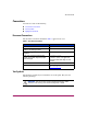
About this Guide Conventions Conventions consist of the following: ■ Document Conventions ■ Text Symbols ■ Equipment Symbols Document Conventions The document conventions included in Table 1 apply in most cases.
About this Guide Caution: Text set off in this manner indicates that failure to follow directions could result in damage to equipment or data. Note: Text set off in this manner presents commentary, sidelights, or interesting points of information. Equipment Symbols The following equipment symbols may be found on hardware for which this guide pertains. They have the following meanings.
About this Guide Power supplies or systems marked with these symbols indicate the presence of multiple sources of power. WARNING: To reduce the risk of personal injury from electrical shock, remove all power cords to completely disconnect power from the power supplies and systems. Any product or assembly marked with these symbols indicates that the component exceeds the recommended weight for one individual to handle safely.
About this Guide Getting Help If you have a question after reading this guide, contact an HP authorized service provider or access our website at http://www.hp.com. HP Technical Support In North America, call technical support at 1-800-652-6672, available 24 hours a day, 7 days a week. Note: For continuous quality improvement, calls may be recorded or monitored. Outside North America, call technical support at the nearest location.
About the MSA SAN Switch 2/8 1 The HP StorageWorks MSA SAN Switch 2/8 is a high-performance, 2 Gb/s, 8 port Fibre Channel switch, designed specifically for installation in the Modular SAN Array 1000 (MSA1000) storage device, to connect the MSA1000 to hosts and Enterprise Backup Solutions in a Storage Area Network (SAN). The MSA1000 provides two slots for embedded interconnect devices.
About the MSA SAN Switch 2/8 Each switch is assigned a system-generated name, dependant on the slot in which it is installed. Table 2: System Assigned Switch Names MSA1000 Sot Location Switch Name Primary (rear-left) MSA1000 Controller Name-switch1 Secondary (rear-right) MSA1000 Controller Name-switch2 Note: The first portion of the switch name is the name assigned to the MSA1000 Controller installed in the associated controller slot.
About the MSA SAN Switch 2/8 MSA SAN Switch 2/8 Firmware Features ■ Universal and self-configuring optical ports for the following protocols: — E_Port (expansion port) — F_Port (fabric port that is not loop capable) — FL_Port (fabric port that is loop capable) ■ Automatic re-routing through the Fabric Shortest Path First (FSPF) algorithm ■ Application Programming Interface (API) that allows applications to interface with switch services ■ Per port statistics for diagnosing and isolating problem port
About the MSA SAN Switch 2/8 MSA SAN Switch 2/8 Hardware Features MSA SAN Switch hardware support includes: ■ Embedded design specifically for the MSA1000 ■ Hot-pluggability The switch can be installed or replaced without power cycling the MSA1000. When adding or replacing a switch, allow sufficient time to complete the POST tests and the configuration tasks before using. ■ Redundancy In redundant fabric configurations, you can install two MSA SAN Switches to support the redundant MSA1000 controllers.
About the MSA SAN Switch 2/8 MSA SAN Switch 2/8 Panel Description Figure 2 is an illustration of the MSA SAN Switch. The switch panel houses the seven available fiber optic ports, the Ethernet port, the serial port, and the corresponding LEDs.
About the MSA SAN Switch 2/8 LEDs The LEDs on the switch provide activity or status information. For detailed information on all of the switch LEDs, see “Configuring the MSA SAN Switch 2/8.” Optical Ports All optical ports support full fabric capability, allowing the MSA SAN Switch to link or cascade to other HP StorageWorks Fibre Channel switches, building a highly scalable SAN fabric. The optical ports are connected via Small Form Factor Pluggable (SFP) media, which are universal and self-configuring.
About the MSA SAN Switch 2/8 Ethernet Port This connector is used to connect the switch to the SAN management network. Switch configuration and management tasks can be made through the Ethernet port either by using a telnet connection to access the CLI or by using a standard web browser to access the Web Tools graphical user interface. By default, the switch is configured to use an IP address of 10.77.77.77. See “Configuring the MSA SAN Switch 2/8” for information on setting the IP address.
About the MSA SAN Switch 2/8 20 MSA SAN Switch 2/8 Installation Guide
Installing the MSA SAN Switch 2/8 2 This chapter discusses the following topics: ■ Verifying Carton Contents, page 22 ■ Installing the MSA SAN Switch 2/8 in the MSA1000, page 23 ■ Installing an SFP Module, page 27 MSA SAN Switch 2/8 Installation Guide 21
Installing the MSA SAN Switch 2/8 Verifying Carton Contents Unpack and inspect the MSA SAN Switch carton contents. Verify that the carton contains the items shown in Figure 3 and listed in the supporting table. Note: If any items are damaged or missing, contact HP or an HP Authorized reseller.
Installing the MSA SAN Switch 2/8 Installing the MSA SAN Switch 2/8 in the MSA1000 Caution: To prevent static shock, which can damage electrical equipment, use industry accepted handling practices when unpacking and moving the switch. See the “Electrostatic Discharge” appendix for more information. Note: The MSA SAN Switch is a hot-pluggable component of the MSA1000 and can be installed and uninstalled regardless of whether the MSA1000 is powered on.
Installing the MSA SAN Switch 2/8 1. If the MSA SAN Switch is replacing the provided Modular SAN Array Fibre Channel I/O Module in the primary slot of the MSA1000, remove the I/O Module from the bay. To remove the I/O module, slide and hold the latch on the I/O Module to the right and then grasp the handle and pull the I/O Module straight out of the bay. See Figure 4 for an illustration.
Installing the MSA SAN Switch 2/8 3. Insert the MSA SAN Switch into the vacated slot of the MSA1000. To insert the switch, orient the switch with the handle on the right and insert the edge that contains the rear backplane interface connector into the bay until the connector seats and the latch clicks. See Figure 5 for an illustration. Figure 5: Inserting the MSA SAN Switch 2/8 into the vacant slot If the MSA1000 is powered on, the MSA SAN Switch is powered on as soon as it is installed.
Installing the MSA SAN Switch 2/8 4. For redundant-controller configurations only: If an MSA SAN Switch is being installed in the secondary slot, remove the blanking panel and install the switch in the open slot, as previously illustrated in step 2 and step 3. To remove the blanking panel, loosen the thumbscrew that holds the blanking panel in place and remove the blank from the back of the unit. See Figure 6 for an illustration of removing the blanking panel.
Installing the MSA SAN Switch 2/8 Installing an SFP Module Use these steps to connect the SFPs in the ports of the MSA SAN Switch, as required. 1. Remove the shipping plugs from the appropriate ports on the switch panel. 2. Position the SFP so the key (the tab near the cable-end of the SFP) is on top. 3. Insert the SFP into the port until it is firmly seated and the latching mechanism clicks. Note: The SFP is keyed so that it can only be inserted with the correct orientation into the port.
Installing the MSA SAN Switch 2/8 Note: For dust and ESD (electrostatic discharge) protection, a cover is provided for each optical port and should be kept on the port whenever the port is not in use. Caution: Do not connect the switch to a configured SAN without first configuring the switch. 4. Connect the cables to the SFPs as appropriate to the fabric topology, by positioning each cable so that the key (the ridge on one side of the cable connector) is aligned with the slot in the SFP.
Configuring the MSA SAN Switch 2/8 3 The process of configuring the MSA SAN Switch includes the initial process of changing the factory-set IP address to a valid IP address for your environment. The IP address must initially be entered using the CLI. After the IP address is set, additional parameters must be entered, but they may be entered through either the CLI or the Web Tools.
Configuring the MSA SAN Switch 2/8 Requirements The following items are required to set network addressing: ■ An IP address from your Network Administrator ■ An installed MSA SAN Switch ■ Serial cable (supplied with the switch) for connecting the switch to the workstation This cable must be a straight-through cable.
Configuring the MSA SAN Switch 2/8 Entering Initial Configuration Settings through the CLI Initial switch configuration includes: ■ Accessing the CLI ■ Setting Network Addresses Accessing the CLI Depending on your environment and preference, you may access the CLI through either the serial port or through the Ethernet port (via a telnet session). Instructions for accessing the CLI through each of these methods is detailed in the following paragraphs.
Configuring the MSA SAN Switch 2/8 5. Establish a connection from the workstation to the switch using a terminal emulation application such as ProComm or Hyper Terminal. ■ In a Windows environment, enter the following settings: Table 3: Serial Port Settings ■ Parameter Value Bits per second 9600 Databits 8 Parity None Stop bits 1 Flow control None In a Tru64 UNIX environment, enter the following command: tip /dev/ttyb -9600 6.
Configuring the MSA SAN Switch 2/8 Accessing the CLI through the Ethernet Port (via a Telnet Session) Use these steps to log into the MSA SAN Switch from the Ethernet port. 1. Remove the shipping plug from the MSA SAN Switch Ethernet port. 2. Connect one end of an Ethernet cable to the workstation or to an Ethernet network containing the workstation. 3. Connect the other end of the Ethernet cable to the MSA SAN Switch Ethernet port.
Configuring the MSA SAN Switch 2/8 Setting Network Addresses Use the following steps to enter the MSA SAN Switch IP address, subnetmask, and gateway address. Note: During first time setup, you must replace the factory IP address, subnetmask and gateway address with addresses provided by your Network Administrator. 1. Log on to the switch using the admin log on. See “Accessing the CLI” for instructions. 2. Enter the following command at the prompt: ipAddrSet 3.
Configuring the MSA SAN Switch 2/8 Connecting the MSA SAN Switch 2/8 to the Ethernet Network If you have not yet connected the MSA SAN Switch to the Ethernet segment: 1. Remove the shipping plug from the MSA SAN Switch Ethernet port. 2. Connect one end of an Ethernet cable to the workstation or to an Ethernet network containing the workstation. 3. Connect the other end of the Ethernet cable to the MSA SAN Switch Ethernet port.
Configuring the MSA SAN Switch 2/8 Completing MSA SAN Switch 2/8 Configuration After connecting the cables and entering the IP address information, additional parameters must be set. Some of these tasks include setting the system date and time, setting up zoning information, and backing up the system configuration settings. Note: HP strongly recommends backing up the configuration. This ensures that a complete configuration is available if required for a replacement switch.
Managing the MSA SAN Switch 2/8 4 This chapter discusses the following management topics: ■ Command Line Interface (CLI) Overview, page 39 ■ Web Tools Overview, page 40 ■ Optional Management Tools, page 42 ■ LED Activity Definitions, page 45 ■ MSA SAN Switch 2/8 POST and Diagnostic Tests, page 48 MSA SAN Switch 2/8 Installation Guide 37
Managing the MSA SAN Switch 2/8 The management functions of the MSA SAN Switch 2/8 allow you to monitor fabric topology, port status, physical status, and other information to aid in system debugging and performance analysis.
Managing the MSA SAN Switch 2/8 Command Line Interface (CLI) Overview As already detailed, the CLI must be used to initially set the IP address of the switch. In addition to this initial configuration task, this user interface can be used to complete the switch configuration and perform maintenance tasks. All MSA1000 supported operating systems can use the CLI to manage their switch.
Managing the MSA SAN Switch 2/8 Web Tools Overview Web Tools provides a graphical user interface that allows the administrator to monitor and manage entire fabrics and individual switches and ports from any standard workstation. Using a standard Web browser with a JavaTM Plug-in, Web Tools can be used to manage the MSA SAN Switch either locally or remotely. Note: Web Tools can be run from any workstation that supports a Java Runtime Environment version JRE 1.2.-008 or later.
Managing the MSA SAN Switch 2/8 Figure 9: Initial Web Tools display All switches in the fabric are displayed in the Web Tools main window, including switches that do not have a Web Tools license. However, only switches that have a Web Tools license can be managed through the Web Tools GUI. Note: The switch panel image in the documentation is a representation of the switch. The switch panel on your screen display will accurately represent your switch.
Managing the MSA SAN Switch 2/8 Optional Management Tools Your MSA SAN Switch includes the Web Tools and Advanced Zoning components. These tools were enabled at the factory with a software license key. In addition to Web Tools and Advanced Zoning, the MSA SAN Switch supports the following optional management tools: ■ ISL Trunking ■ QuickLoop ■ Fabric Watch ■ Advanced Performance Monitoring ■ Extended Fabrics Note: Each management tool requires a license.
Managing the MSA SAN Switch 2/8 QuickLoop The optional QuickLoop feature allows arbitrated loops to attach to a fabric. Without modifying their drivers, private targets on the arbitrated loops can be accessed by public or private hosts elsewhere on the fabric. Advantages to integrating QuickLoop into your SAN include: ■ Supports communication between devices that are not fabric-aware.
Managing the MSA SAN Switch 2/8 Extended Fabrics The optional Extended Fabrics feature increases the maximum bandwidth between two switches (at extended distances). Advantages to integrating Extended Fabrics into your SAN include: ■ Provides the highest possible performance of data transfer between switches. ■ Provides maximum buffering between E_Ports connected over an extended distance For more information, refer to the HP StorageWorks Extended Fabric User Guide.
Managing the MSA SAN Switch 2/8 LED Activity Definitions MSA SAN Switch activity and status can be determined through the activity of the LEDs on the switch panel. The LEDs will flash green, yellow, or amber while the switch is booting and while POST or other diagnostic tests are running. These patterns are normal and do not indicate a problem. Wait until POST or other diagnostic tests are completed before examining and interpreting the LEDs.
Managing the MSA SAN Switch 2/8 Switch Readiness LED Definitions Table 4: Switch Readiness LED Definitions LED Color Hardware Status Recommended Action No light Switch has no power. Verify switch is installed correctly. Steady green Switch is on and all ports are ready for use. No action required. Steady yellow One or more ports are offline Verify the switch has completed booting and is not disabled. If light is still yellow, check the error log and the Port Status LEDs.
Managing the MSA SAN Switch 2/8 Port Status LED Definitions Table 6: Port Status LEDs LED Color Hardware Status Recommended Action No light No signal or light carrier (media or cable) detected. Check media and cable. Steady green Port is online (connected to external device) but shows no traffic. No action required. Slow-flashing green (on 1 second; off 1 second) Port is online, but segmented, indicating a loopback cable or incompatible switch. Verify correct device is connected to the port.
Managing the MSA SAN Switch 2/8 MSA SAN Switch 2/8 POST and Diagnostic Tests Read the following sections for information on the POST and diagnostic tests. POST Results Each time the MSA1000 is powered on or the MSA SAN Switch is reset or reseated, the switch automatically performs a Power-on Self-Test (POST), verifying that the switch is operating properly. During POST, the port status LEDs flash. POST completes in approximately seven minutes.
Managing the MSA SAN Switch 2/8 Diagnostic Tests Diagnostic tests are provided to help troubleshoot the hardware and the firmware. The diagnostic tests provided on the switch include tests of internal connections and circuitry, fixed media, and any SFP modules and fiber optic cables in use. The tests are implemented by command, either through a telnet session or a serial connection. All diagnostic tests are run at link speeds of both 1 Gbps and 2 Gbps.
Managing the MSA SAN Switch 2/8 50 MSA SAN Switch 2/8 Installation Guide
Backing Up Configuration Data and Upgrading Firmware 5 This chapter discusses the following topics: ■ Backing Up System Configuration Settings, page 52 ■ Restoring System Configuration Settings, page 53 ■ Upgrading or Restoring the Switch Firmware, page 54 MSA SAN Switch 2/8 Installation Guide 51
Backing Up Configuration Data and Upgrading Firmware Backing Up System Configuration Settings HP strongly recommends saving the configuration after the initial configuration is completed and periodically thereafter. The FTP or the RSHD protocols may be used to backup the system configuration. Note: The two supplied utilities, RSHD.EXE and CAT.EXE are available from the HP support website at http://www.hp.com. Use these steps to upload a backup copy of the configuration settings to a host computer. 1.
Backing Up Configuration Data and Upgrading Firmware Restoring System Configuration Settings Use these steps to restore the system configuration settings from a backup. 1. Verify that the RSHD service or the FTP service is running on the host computer. 2. Log in to the switch as the admin user. 3. At the command line, shut down the switch by entering: SWITCHDISABLE Because the switch is disabled, a warning message about the switch status is displayed. 4.
Backing Up Configuration Data and Upgrading Firmware Upgrading or Restoring the Switch Firmware The MSA SAN Switch ships with preloaded firmware. In most cases, it is not necessary to update the firmware on a new switch. The firmware version can be obtained and downloaded as follows: ■ Downloading New Switch Firmware through the CLI ■ Downloading New Switch Firmware through Web Tools Each of these methods is discussed in the following sections.
Backing Up Configuration Data and Upgrading Firmware Performing a Firmware Upgrade through the CLI Use these steps to upgrade or restore the switch firmware: 1. Verify that the RSHD service or the FTP service is running on the host computer. 2. Download the firmware from the HP Website at http://www.hp.com. Go to the Support page for the required loaders and instructions. 3. Log in to the switch as the admin user. 4.
Backing Up Configuration Data and Upgrading Firmware Downloading New Switch Firmware through Web Tools Before you upgrade the firmware on your switch, verify version of the firmware you are currently using. Determining Your Firmware Version through Web Tools To view the current version of the firmware on the switch: 1. Access Web Tools. The Fabric View is displayed by default. A panel for each switch in the fabric is displayed on the screen. Figure 11 is an illustration of the Web Tools Fabric View.
Backing Up Configuration Data and Upgrading Firmware 2. Locate the panel for this switch and view the display. If necessary, click the Detail View button to display more information. The following information is displayed for the switch: ■ Name ■ Fabric OS version ■ Domain ID ■ Ethernet IP ■ Ethernet Mask ■ FCnet IP ■ FCnet Mask ■ Gateway IP ■ WWN Performing a Firmware Upgrade through Web Tools To download the latest version of the firmware on the switch: 1.
Backing Up Configuration Data and Upgrading Firmware Figure 12: Firmware Upgrade tab 5. Select the Firmware Download function. 6. Modify the Host IP address to indicate the host with the firmware. 7. Modify the Filename to indicate the path and filename of the firmware. 8. Select the Fastboot After Download boot option. 9. Select Apply. Wait for the firmware download to complete and the switch to restart.
Regulatory Compliance Notices A Regulatory Compliance Identification Numbers For the purpose of regulatory compliance certifications and identification, your HP StorageWorks MSA SAN Switch 2/8 is assigned an HP series number. The HP series number for this product is: Series EK 1506. The series number can be found on the product label, along with the required approval markings and information. When requesting certification information for this product, always refer to this series number.
Regulatory Compliance Notices Class A Equipment This equipment has been tested and found to comply with the limits for a Class A digital device, pursuant to Part 15 of the FCC Rules. These limits are designed to provide reasonable protection against harmful interference when the equipment is operated in a commercial environment.
Regulatory Compliance Notices European Union Notice Products with the CE Marking comply with both the EMC Directive (89/336/EEC) and the Low Voltage Directive (73/23/EEC) issued by the Commission of the European Community.
Regulatory Compliance Notices Japanese Notice 62 MSA SAN Switch 2/8 Installation Guide
Regulatory Compliance Notices Laser Devices All HP systems equipped with a laser device comply with safety standards, including International Electrotechnical Commission (IEC) 825. With specific regard to the laser, the equipment complies with laser product performance standards set by government agencies as a Class 1 laser product. The product does not emit hazardous light; the beam is totally enclosed during all modes of customer operation and maintenance.
Regulatory Compliance Notices Laser Product Label The following label or equivalent is located on the surface of the HP supplied laser device. This label indicates that the product is classified as a CLASS 1 LASER PRODUCT. This label appears on a laser device installed in your product. Laser Information The following table lists laser specifications. Table 7: Laser Specifications Item 64 Specification Wave length 850 nm ± 35 nm Divergence angle 53.5 degrees ± 4.5 degrees Output power Less than 2.
Electrostatic Discharge B To prevent damaging the system, be aware of the precautions you need to follow when setting up the system or handling parts. A discharge of static electricity from a finger or other conductor may damage system boards or other static-sensitive devices. This type of damage may reduce the life expectancy of the device. To prevent electrostatic damage, observe the following precautions: ■ Avoid hand contact by transporting and storing products in static-safe containers.
Electrostatic Discharge Grounding Methods There are several methods for grounding. Use one or more of the following methods when handling or installing electrostatic-sensitive parts: ■ Use a wrist strap connected by a ground cord to a grounded workstation or computer chassis. Wrist straps are flexible straps with a minimum of 1 megohm ± 10 percent resistance in the ground cords. To provide proper ground, wear the strap snug against the skin.
I/O Connection Specifications C This appendix covers the following topics: ■ The serial port can be used to connect the switch to a computer workstation to configure the switch IP address without connecting to the fabric. The serial port’s parameters are 9600 baud, 8 data bits, no parity, 1 stop bit, and no flow control.
I/O Connection Specifications Ethernet Port Specifications The Ethernet port uses the pin layout specified in Table 9. Table 9: Ethernet Port Cabling Pin Layout Pin Signal Function 1 TX+ Transmit data 2 TX- Transmit data 3 RX+ Receive data 4 NC 5 NC 6 RX- 7 NC 8 NC 9 NC Receive data Note: For dust and ESD (electrostatic discharge) protection, a cover is provided for the Ethernet port and should be kept on the port whenever the Ethernet port is not in use.
index A configuration settings backing up 52 restoring 53 connection protocols, supported 15 conventions document 9 equipment symbols 10 text symbols 9 Advanced Performance Monitoring 43 arbitrated loop 43 audience 8 authorized reseller, HP 12 automatic self-discovery 15 B C Declaration of Conformity 60 description of switch 13 diagnostic tests 49 displaying installed feature licenses 44 document conventions 9 related documentation 8 cables FCC compliance statement 60 Canadian Notice (Avis Canadien) 6
Index F F_Port connection protocol 15 Fabric Watch 43 fastboot 48 FCC class A compliance notice 60 firmware downloading from the HP website 55, 57 features, listed 15 upgrading through the CLI 55 upgrading through Web Tools 57 version viewing in the CLI 54 viewing in Web Tools 56 FL_Port connection protocol 15 front panel, LED locations 45 G gateway address, setting in the CLI 34 getting help 12 grounding methods 66 H hardware features, listed 16 help, obtaining 12 hot-pluggability 16, 23 HP authorized r
Index N name of switch 14 network addressing, requirements 30 numbering sequence of ports 18 O optical ports, see Ports optional management tools 42 P panel description 17 detailed view 17 password, in the CLI 32, 33 pin layout Ethernet port 68 serial port 67 port speed LED illuminations 46 port status LED illuminations 47 ports Ethernet connecting 35 location 17 optical location 17 numbering sequence 18 speed negotiation 18 serial configuring for use 31 described 19 location 17 port settings 32 UNIX set
Index U W UNIX, serial port settings 32 upgrading the firmware 54 user ID, in the CLI 32, 33 warning rack stability 11 symbols on equipment 10 Web Tools managing by 38 overview 40 upgrading the firmware 57 website, HP storage 12 V verifying operation 36 version of firmware viewing in the CLI 54 viewing in Web Tools 56 Z zoning, described 15 72 MSA SAN Switch 2/8 Installation Guide