HP StorageWorks Simple SAN Connection Manager user guide Part number: 5697-0083 Fifth edition: July 2009
Legal and notice information © Copyright 2008–2009 Hewlett-Packard Development Company, L.P. Confidential computer software. Valid license from HP required for possession, use or copying. Consistent with FAR 12.211 and 12.212, Commercial Computer Software, Computer Software Documentation, and Technical Data for Commercial Items are licensed to the U.S. Government under vendor's standard commercial license. The information contained herein is subject to change without notice.
Contents About this guide . . . . . . . . . . . . . . . . . . . . . . . . . . . . . . . . . . . . . . . . . . . . . . . . . . . . . . . 9 Intended audience . . . . . . . . . . . . . . . . . . . . . . . . . . . . . . . . . . . . . . . . . . . . . . . . . . . . . . . . . . . Prerequisites. . . . . . . . . . . . . . . . . . . . . . . . . . . . . . . . . . . . . . . . . . . . . . . . . . . . . . . . . . . . . . . . Related documentation . . . . . . . . . . . . . . . . . . . . . . . . . . . . . . . . . . . . . .
5 Managing switches . . . . . . . . . . . . . . . . . . . . . . . . . . . . . . . . . . . . . . . . . . . . . . . . . 49 About transparent routing . . . . . . . . . . . . . . . . . . . . . . . . . . . . . . . . . . . . . . . . . . . . . . . . . . . . . . . . . Viewing switch properties . . . . . . . . . . . . . . . . . . . . . . . . . . . . . . . . . . . . . . . . . . . . . . . . . . . . . . . . . Description of the switch properties . . . . . . . . . . . . . . . . . . . . . . . . . . . . . . . . . . . . .
Configuring a storage subsystem . . . . . . . . . . . . . . . . . . . . . . . . . . . . . . . . . . . . . . . . . . . . . . . . . . . 121 Configuration using a pre-defined application template . . . . . . . . . . . . . . . . . . . . . . . . . . . . . . . . . 121 Configuration using a customized deployment. . . . . . . . . . . . . . . . . . . . . . . . . . . . . . . . . . . . . . . . 125 A Troubleshooting . . . . . . . . . . . . . . . . . . . . . . . . . . . . . . . . . . . . . . . . . . . . . . . . . . .
48 Enter HBA Server Name and OS Type dialog box . . . . . . . . . . . . . . . . . . . . . . . . . . . . . . . . . . . . . 81 49 HBA Server Name and OS Type dialog box . . . . . . . . . . . . . . . . . . . . . . . . . . . . . . . . . . . . . . . . . 82 50 Logical Disk (LUN) Information . . . . . . . . . . . . . . . . . . . . . . . . . . . . . . . . . . . . . . . . . . . . . . . . . . 83 51 New Logical Disk Parameters dialog box (EVA storage) . . . . . . . . . . . . . . . . . . . . . . . . . . . . . . . . .
Tables 1 2 3 4 5 6 7 Document conventions . . . . . . . . . . . . . . . . . . . . . . . . . . . . . . . . . . . . . . . . . . . . . . . . . . . . . . . . . 10 File menu . . . . . . . . . . . . . . . . . . . . . . . . . . . . . . . . . . . . . . . . . . . . . . . . . . . . . . . . . . . . . . . . . . 31 Logical Disk Operations menu . . . . . . . . . . . . . . . . . . . . . . . . . . . . . . . . . . . . . . . . . . . . . . . . . . . . 31 Advanced Operations menu . . . . . . . . . . . . . . . . . . . . . . .
About this guide This guide provides information about: • Installing, upgrading, and removing HP StorageWorks Simple SAN Connection Manager (hereafter referred to as Simple SAN Connection Manager) • Viewing and managing storage area network (SAN) connections (switches, servers, subsystems, HBAs, and logical disks) • Troubleshooting Simple SAN Connection Manager Intended audience This guide is intended for network administrators who use the Simple SAN Connection Manager software to view and manage their SAN
Document conventions and symbols Document conventions Table 1 Convention Element Medium blue text: Figure 1 Cross-reference links and e-mail addresses Medium blue, underlined text (http://www.hp.
• Product serial numbers • Product model names and numbers • Applicable error messages • Operating system type and revision level • Detailed, specific questions For continuous quality improvement, calls may be recorded or monitored. Product warranties For information about HP StorageWorks product warranties, see the warranty information website: http://www.hp.com/go/storagewarranty Subscription service HP strongly recommends that customers sign up online using the Subscriber’s choice website: http://www.
1 Introduction Simple SAN Connection Manager is a GUI-based management application for basic handling of SAN components such as host bus adapters (HBAs), switches, and storage arrays (also referred to as “subsystems” in this guide). For managing storage arrays, it uses Microsoft’s Virtual Disk Service (VDS). Simple SAN Connection Manager provides simplified storage management for VDS-compliant storage devices in a single, integrated, wizard-based user interface.
• “Troubleshooting,” page 133, provides solutions to some common issues you might encounter. • “Glossary,” page 139, defines terms used in this guide. In addition, at the end of this guide is an index to help you easily locate information. What’s new in this release Simple SAN Connection Manager version 2.
2 Installing, upgrading, and removing Simple SAN Connection Manager This chapter provides procedures for installing and upgrading Simple SAN Connection Manager on a Windows management station, and for installing and upgrading the required software components on other servers. It also provides procedures for removing Simple SAN Connection Manager from a Windows system, as well as removing the software components from Linux servers.
Figure 2 Installation wizard: options 4. Select one of the following product installation options: • Management Installation Installs all components required for a management station with both Enterprise Virtual Array (EVA) and Modular Smart Array (MSA) storage. With the Management Installation, you can also select one or both of the following optional components: • HP StorageWorks SAN Designer provides quick and easy ways to design SANs based on your specific performance, cost, and future storage needs.
Figure 3 Installation wizard: Available Storage Subsystem 6. Select one or more types of storage subsystems (EVA and MSA) that exist in your SAN by choosing Yes from the drop-down menu for the appropriate subsystem types. Then click OK to close this dialog box and continue the installation. The progress window monitors the installation.
Figure 4 Installation wizard: Add EVA Management Account 8. Before installation can proceed, you must add a user account to the HP Storage Admin user group. (This step is not necessary for MSA storage.) Choose one of the following options: • If you do not already have any user accounts set up, create a user account now by completing the User name, Password, and Confirm Password boxes. Then click Create User and Add to Group.
To install the components required by Simple SAN Connection Manager on Linux: 1. Insert the installation CD into the CD-ROM drive of the server.
4. If the following message appears at the end of the installation, you must restart the computer, otherwise, continue with step 6: New driver and qlremote installed but not active. For new driver and qlremote to be active either: Reboot the system (Mandatory in case of Boot From SAN) or Stop all the applications using QLogic driver. Unload QLogic driver by executing following command: # modprobe -r qla2XXX (ex.
Emulex HBA configuration Simple SAN Connection Manager can manage all of your supported Windows and Linux servers that have Emulex HBAs installed. In order for the application to properly identify your server(s), you must set the EnableFDMI parameter on the Emulex HBA. Use the HBAnyware software to set the EnableFDMI parameter to a value of 2. For detailed instructions on how to enable the FDMI parameter on your Emulex HBA, see your HBA documentation.
2. Click Upgrade. A message box prompts you to confirm that you want to upgrade an existing version of Simple SAN Connection Manager. 3. To continue with the upgrade, click Yes. The end user license agreement is displayed. 4. Read the text of the HP end user license agreement, and then either click Agree to start the software upgrade or Disagree to cancel the upgrade. The installation upgrade checking components window opens while the wizard looks for components that cannot be upgraded.
Figure 7 Installation upgrade wizard: Add EVA Management Account 7. Before the installation upgrade can proceed, you must add a user account to the HP Storage Admin user group. (This step is not necessary for MSA storage.) Choose one of the following options: • If you already have one or more user accounts set up (for example, you may have set up accounts when you installed your EVA), select one to add to the HP Storage Admin group. Then click Add To Group.
Figure 8 Installation upgrade wizard: finished with errors 8. Click the View Error Log link to open an error log that provides additional information. You may be prompted to upgrade, add, or modify components for successful installation. 9. Remove the Simple SAN Connection Manager CD, and then click Reboot. 10. Restart your computer to complete the installation process. 11. When you restart your computer, the system may report finding new hardware. If so, respond to these messages by clicking Cancel.
If this occurs, the CD may get mounted with the no execution flag, causing the installation script to fail. Installation failure may be indicated by the following error message: # ./install_smb.sh The following is returned: bash: ./install_smb.sh: /bin/sh: bad interpreter: Permission denied The workaround is to manually mount the installation CD. For example, if the CD was auto-mounted in /media/HpInstallx.x, issue these commands to unmount, and then remount the CD: # unmount /media/HpInstallx.
The following is returned: qla2xxx_conf qla2xxx scsi_mod 303752 982688 445298 1 0 qla2xxx c. To verify that the correct driver is loaded, issue the following command: # cat /proc/scsi/qla2xxx/* | grep "Driver version" The following is returned: Firmware version: 3.03.25 IPX Driver version: 8.02.02-fo Removing Simple SAN Connection Manager The Simple SAN Connection Manager uses the installation wizard to remove all components currently installed. You must reboot your computer following program removal.
The program removal progress window opens and monitors the product removal. A progress bar shows the percent of the uninstallation completed and icons show the status of each component as it is removed, for example: • A icon next to the component name indicates successful removal. • A icon next to the component indicates that it has not yet been removed. • A icon indicates that an error occurred during removal of this component. When program removal is complete, you must reboot the computer. 4.
Installing, upgrading, and removing Simple SAN Connection Manager
3 Getting started This chapter covers basic information to help you get started using Simple SAN Connection Manager, and includes these sections: • “Understanding the user interface” on page 29 introduces you to the main application window, menu bar, and toolbar buttons. • “Using the help system” on page 34 explains how to access and use the context-sensitive help.
Menu Bar Toolbar Navigation Pane Content Pane Figure 10 Simple SAN Connection Manager user interface Menu bar The Simple SAN Connection Manager menu bar contains the following menus, each of which is described in detail in this section: • “File menu,” page 31 • “Logical Disk Operations menu,” page 31 • “Advanced Operations menu,” page 32 • “HBA & Switch Management menu,” page 32 • “Help menu,” page 33 30 Getting started
File menu Table 2 provides a brief description of the items on the File menu and a reference to more detailed information. Table 2 File menu Menu Item Purpose See Save current SAN connection Saves a graphical topology of your SAN to reference against any changes made to your system. “Saving the current configuration” on page 46.
Advanced Operations menu Table 4 provides a brief description of the items on the Advanced Operations menu and a reference to more detailed information. Table 4 Advanced Operations menu Menu Item Purpose See Create & Manage Partition Initialize a new disk; create, modify, or delete partitions of initialized disks. “Creating and managing partitions” on page 105.
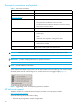
Table 5 HBA & Switch Management menu (continued) Menu Item Purpose See Get Network Properties Displays network information. “Viewing network properties” on page 50. Set Switch IP Address Changes the switch IPv4 or IPv6 address. “Setting the switch IP address” on page 55. Set Switch IPsec Information Manages a list of IP security associations and policies. “Setting switch IP security” on page 64 Update Switch Firmware Updates the switch with a new firmware image file.
Table 7 Toolbar buttons (continued) Button Purpose Delete a logical disk Create and manage partitions Manage the storage subsystem Refresh the server list Refresh the subsystem list Open the About box Using the help system The Simple SAN Connection Manager’s help system provides quick access to information about performing tasks and completing dialog boxes. To access the help system from Simple SAN Connection Manager, choose one of the following options: • On the Help menu, click Contents.
Starting Simple SAN Connection Manager Follow these steps to start Simple SAN Connection Manager. You will need to perform some of these steps only the first time you start the application. To start Simple SAN Connection Manager: 1. To launch the application, choose one of the following options: • Click Start, point to All Programs > Hewlett-Packard > HP StorageWorks Simple SAN Connection Manager, and then click HP StorageWorks Simple SAN Connection Manager.
4. Wait while the application discovers (detects) switches, servers, storage subsystems, and logical disks. This may take a few minutes. If the application detects a new, unconfigured switch in your SAN, the New Switch Setup dialog box (Figure 12) opens. Figure 12 New Switch Setup dialog box The New Switch Setup dialog box prompts you to set up the new switch by completing these three steps: 1. Set switch IP address 2. Set switch administrator password 3. Set switch zoning: HBA zoning 5.
Figure 13 Set Switch IP Address dialog box: new switch setup 6. Select either the Enable IPv4 or Enable IPv6 check box, and then complete the appropriate IPv4 or IPv6 information (for details, see “Setting the switch IP address” on page 55). Click OK. The New Switch Setup dialog box now shows a check mark next to the first step, “Set switch IP address,” (Figure 14) indicating that you have completed that task. Figure 14 First step of New Switch Setup completed 7.
Figure 15 Set Switch Admin Password dialog box: new switch setup 8. In the Set Switch Admin Password dialog box, complete the following steps: a. Enter the Old Password (the factory default password for the switch is password). b. Enter a New Password (at least 8 alphanumeric characters). c. Re-enter the new password in the Verify Password box. d. To set the switch admin password, click OK. To cancel password setup, click Cancel. 9. A message box confirms successful password change completion.
Figure 17 Set the Switch Default Zoning dialog box: new switch setup The Set the Switch Default Zoning dialog box contains the following information: • Default zone set name—Shows the default name for the current switch zoning configuration. • Zone List—Shows the existing HBA zones with its HBA adapter and devices. If a zone list is closed (the Switch Port #, Type, and Vendor information is hidden), click the plus mark (+) to open it.
13. If Simple SAN Connection Manager detects another unconfigured switch, the New Switch Setup wizard opens again for that switch and guides you through its setup. After you have either completed all the steps required in the New Switch Setup procedures (step 4 through step 9), or opted not to set up the switch at this time, the Welcome… Configure Your SAN dialog box (Figure 19) appears. Figure 19 Welcome… Configure Your SAN dialog box 14.
Figure 20 Perform Other Operations dialog box 15. If you clicked Perform Other Operations on the Welcome... Configure Your SAN dialog box, select from these common SAN configuration operations: Logical Disk and Partition Operations: • Click Assign Logical Disk to Server to open the Logical Disk Server Presentation dialog box (see “Assigning and unassigning a logical disk to a server” on page 95).
• Click Update HBA Driver to open the HBA Driver Update wizard (see “Updating an HBA driver” on page 78). 16. To exit this dialog box without performing any configuration, and view the Simple SAN Connection Manager main window, click Close. (All configuration options offered on this dialog box are also available from the main window.
4 Viewing maps, events, and configurations This chapter provides procedures that describe the following options: • “Viewing a Physical Connection map,” page 43 • “Viewing a LUN Assignment map,” page 44 • “Viewing the event log,” page 45 • “Saving and comparing SAN configurations,” page 46 Viewing a Physical Connection map Simple SAN Connection Manager provides a graphical representation of physical connections among the storage subsystems, switches, and HBAs within the SAN.
NOTE: The information presented is read-only. You can right-click any of the icons representing switches, HBAs, servers, and subsystems to open a shortcut menu for that component. How to view a Physical Connection map To view a physical connection map: 1. In the navigation pane, click on the root of the navigation pane: • If the navigation pane displays the Storage Subsystem - Logical Disk View, the root is called Subsystem - Logical Disk.
• If the navigation pane displays the Storage Subsystem - Logical Disk View, the root is called Subsystem - Logical Disk. • If the navigation pane displays the Server - Storage View, the root is called Server - Logical Disk. 2. The content pane opens a topology map. If the map shown is Physical Connection map, click the LUN Assignment Map tab to bring that map forward.
To export the event log: 1. On the bottom of the Application Event Log dialog box, click the Export button to open the Export Event Log dialog box. 2. Navigate to the location where you want to save the event log, and then enter a name for the file with either an .XML, .CSV, or .TXT extension. 3. Click Save.
Figure 24 Compare Current and Previous Configuration dialog box This dialog box shows a graphical representation listing: • Removed servers • New servers • New HBAs • Removed switch(es) • New switch(es) • Removed storage subsystem(s) • New storage subsystem(s) 2. When you finish reviewing the dialog box, click Close.
Viewing maps, events, and configurations
5 Managing switches This chapter provides the following procedures for viewing and managing your HP StorageWorks 8/20q Fibre Channel Switches using Simple SAN Connection Manager: • “About transparent routing,” page 49 • “Viewing switch properties,” page 49 • “Viewing network properties,” page 50 • “Viewing switch zoning information,” page 51 • “Setting the switch default zoning,” page 53 • “Setting the switch admin password,” page 55 • “Setting the switch IP address,” page 55 • “Updating switch firmware,”
Figure 25 Switch Properties How to view switch properties To view switch properties: 1. To access the switch properties, choose one of the following options: • On the HBA & Switch Management menu, click Get Switch Properties. If there is only one switch in your SAN, it’s properties appear. If there is more than one switch, the Switch Selection dialog box opens; continue with step 2.
Figure 26 Network Properties How to view network properties To view network properties: 1. To access the switch properties, choose one of the following options: • On the HBA & Switch Management menu, click Get Network Properties. If there is only one switch, the switch is automatically selected; continue with step 3. If there is more than one switch, the Switch Selection dialog box opens; continue with step 2.
Figure 27 Switch Zoning Information dialog box This dialog box shows the following current information about your switch: • Zone List—Lists all zones and the members of each. The currently active zones are shown in a darker color. • Switch Name (Port #)—Shows the switch name and, in parentheses, the number of the switch port that is attached to the HBA or RAID storage device. • Port Type—Shows the type of port; for example, HBA or RAID storage.
Figure 28 Switch Zoning Information dialog box (TR_Ports mapping) Setting the switch default zoning CAUTION: Altering the active zoning configuration can disrupt SAN traffic. A zone is a named group of ports or devices. Members of the same zone can communicate with each other and transmit outside the zone, but cannot receive inbound traffic from outside the zone. Zoning divides the fabric for purposes of controlling discovery and inbound traffic.
If the switch already has an active zoning setup, a message box asks if you want to remove and replace existing zoning with the default HBA-based zoning and advises you to carefully review the current active zoning. Be aware that modifying zoning can disrupt SAN traffic. 2. To close the message box and continue, click Yes. To cancel switch default zoning setup, click No. The Set the Switch Default Zoning dialog box (Figure 29) opens.
Setting the switch admin password Simple SAN Connection Manager provides a quick and easy way to set switch administrator passwords within your SAN. These passwords are required for all update operations to be performed on the switch, including: • Updating firmware • Setting switch symbolic name • Setting domain ID Setting switch admin passwords prevents unauthorized users from performing these operations. To set a switch admin password: 1.
NOTE: stack. If the protocol stack on the switch is currently disabled, setting the switch IP address will enable the To set a switch IP address: 1. To access the Set Switch IP Address dialog box, choose one of the following options: • On the HBA & Switch Management menu, click Set Switch IP Address. • In the content pane’s Physical Connection map, right-click a switch icon to select that specific switch, and then on the shortcut menu, click Set Switch IP Address. 2.
• NDP—Select this option to use Neighbor Discovery Protocol for IPv6, as part of the Stateless Address Autoconfiguration protocol. (If you select NDP, the IPv6 address and gateway boxes become unavailable.) b. If you selected Static for IPv6 Discovery, enter a valid address in the IPv6 Address box. NOTE: Ensure that you append a forward slash (/) and address mask length at the end of the IPv6 address. Valid mask lengths range from 0 through 128.
3. In the Switch Firmware Update wizard’s Available Switch(es) list, select one or more switches for which you want to update the firmware as follows: a. Choose one of the following options: • Select a switch on the Available Switch(es) list, and then click Add. • To select all of the available switches, click Add All. b. Click Next. (Next is disabled until you select at least one switch and add it to the Selected Switch(es) list.
7. In this dialog box, complete these steps: a. Enter the user name and password. b. (Optional) If you want the firmware update to take affect immediately, rather than after the switch power is recycled, select the Apply the new firmware image immediately after successful update check box. c. Click OK. 8. Repeat steps 4 through 7 for each switch you want to update, and then continue with step 9. 9. On the completed Switch Firmware Update wizard window (Figure 34), click Next.
CAUTION: The read community string (“public”) and write community string (“private”) are set at the factory to these well-known defaults and should be changed if SNMP is enabled. If SNMP is enabled (default) and the read and write community strings have not been changed from their defaults, you risk unwanted access to the switch. It is very important that you consider how you want to manage the fabric and what switches you do not want managed through another switch. To set the switch SNMP properties: 1.
Read Community Enter the Read Community password (maximum 32 characters) that authorizes an SNMP agent to read information from the switch. This is a write-only field. The value on the switch and the SNMP management server must be the same. The default is public. Write Community Enter the Write Community password (maximum 32 characters) that authorizes an SNMP agent to write information to the switch. This is a write-only field. This value on the switch and the SNMP management server must be the same.
Setting the switch symbolic name and domain ID Use the Set Switch Symbolic Name and/or Domain ID dialog box to change the symbolic switch name or the domain ID. To change the switch symbolic name and domain ID: 1. To access the Set Switch Symbolic Name and/or Domain ID dialog box, choose one of the following options: • On the HBA & Switch Management menu, click Set Switch Symbolic Name and/or Domain ID.
Set DNS Configuration Figure 37 DNS Properties dialog box 2. Under DNS Options, complete the following: a. To enable DNS on the switch, select the DNS Client check box. To disable DNS on the switch, clear the check box. b. If you enable DNS, in the Local Hostname box, enter a valid local host name. 3. Under DNS Server, complete the following: a.
b. If you selected Static for Server Discovery, optionally enter up to three valid addresses in the DNS Server Address boxes. Use the DNS Search List to specify up to five DNS domain suffixes to be used by the DNS client when attempting to resolve a host name into an IP address. For example, if the DNS Search List includes a single domain name “servers.mycompany.com” and a client attempted to look up the host name “myhost,” the DNS client will first request the IP address of the host name “myhost.
Creating an IPsec association To create an IPsec association: 1. On the HBA & Switch Management menu, click Set Switch IPsec Information. (If you have more than one switch in your SAN, the Switch Selection dialog box prompts you to select a switch, and then click OK.) The IPsec Configuration dialog box opens (Figure 38) and lists the existing IPsec Associations on the left and the existing IPsec Policies on the right. Figure 38 IPsec Configuration dialog box 2. Under IPsec Associations, click Create.
Figure 39 IPsec Association dialog box 3. Complete the IPsec Association dialog box as follows: Name Enter a unique alphanumeric name that starts with a letter, does not contain spaces, and does not exceed 32 characters. You may include the following special characters: ampersand (&), hyphen (-), circumflex (^), and underscore (_). Description (Optional) Enter a description of the IPsec policy. Source Address Enter either a valid IPv4 address, a valid IPv6 address, or a valid DNS host name.
Authentication Select one of the following methods to use to authenticate the source and destination address: • HMAC-MD5—Hash Message Authentication Code Message-Digest Algorithm 5 • HMAC-SHA1—Hash Message Authentication Code Secure Hash Algorithm 1 • HMAC-SHA256—Hash Message Authentication Code Secure Hash Algorithm 1 • AES-XCBC-MAC—Advanced Encryption Standard Extensions Cipher Block Chaining Message Authentication Code • None—Do not authenticate source and destination address Authentication Key (xx) E
CAUTION: Be aware that if you click Cancel on the IPsec Configuration dialog box, all changes you have made to IPsec associations and policies are revoked. That is, all associations and policies that you have created, edited, deleted, copied, or pasted while the IPsec Configuration dialog box was open are nullified. Editing an IPsec association To edit an IPsec association: 1. On the HBA & Switch Management menu, click Set Switch IPsec Information.
To copy and paste an IPsec association: 1. On the HBA & Switch Management menu, click Set Switch IPsec Information. (If you have more than one switch in your SAN, the Switch Selection dialog box prompts you to select a switch, and then click OK.) The IPsec Configuration dialog box opens (see Figure 38 on page 65) and lists the existing IPsec Associations on the left and the existing IPsec Policies on the right. 2. Under IPsec Associations, select the association that you want to copy, and then click Copy.
Creating an IPsec policy To create an IPsec policy: 1. On the HBA & Switch Management menu, click Set Switch IPsec Information. (If you have more than one switch in your SAN, the Switch Selection dialog box prompts you to select a switch, and then click OK.) The IPsec Configuration dialog box opens (Figure 40) and lists the existing IPsec Associations on the left and the existing IPsec Policies on the right. Figure 40 IPsec Configuration dialog box 2. Under IPsec Policies, click Create.
Figure 41 IPsec Policy dialog box 3. Complete the IPsec Policy dialog box as follows: Name Enter a unique alphanumeric name that starts with a letter, does not contain spaces, and does not exceed 32 characters. You may include the following special characters: ampersand (&), hyphen (-), circumflex (^), and underscore (_). Description (Optional) Enter a description of the IPsec policy. Source Address Enter either a valid IPv4 address, a valid IPv6 address, or a valid DNS host name.
Protocol Select one of the following protocols or applications to which to apply IP security: • ICMP—Internet Control Message Protocol • ICMP6—Internet Control Message Protocol for IPv6 • IP4—Internet Protocol, version 4 • TCP—Transmission Control Protocol • UDP—User Datagram Protocol • Any—Any protocol Or enter a number in the range of 0 to 255. If you select ICMP6, you must also enter a value in the ICMP IPv6 Type box.
4. To save the new IPsec policy and close the IPsec Policy dialog box, click OK. To abandon creation of the IPsec policy, click Cancel. 5. When you are through managing security policies, select one of the following options: • To save your changes and close the IPsec Configuration dialog box, click OK. • To close the IPsec Configuration dialog box without saving any changes, click Cancel.
Copying and pasting IPsec polices To simplify the process of creating IPsec policies, you can copy an existing policy, paste it, modify it as needed, and then save it under a new name. For example, if you use the same protocols and keys for all IPsec policies, you can configure one complete policy, and then copy it to create additional policies with different source or destination addresses. To copy and paste an IPsec policy: 1. On the HBA & Switch Management menu, click Set Switch IPsec Information.
6 Managing HBAs This chapter provide procedures for managing your HP StorageWorks HBAs (host bus adapters) using Simple SAN Connection Manager, including: • “Viewing HBA information,” page 75 • “Updating an HBA BIOS image,” page 76 • “Updating an HBA driver,” page 78 • “Creating an alias for an HBA,” page 80 • “Manually entering FDMI information,” page 81 Viewing HBA information Simple SAN Connection Manager provides easy access to information about each HBA within your SAN.
• Driver Version • HBA Connected Target List: • Target Port Name/Subsystem Port (see note) • Node Name • Port ID • Vendor • Product ID NOTE: The Target Port Name/Subsystem Port column lists the names of the target ports connected to the HBA. Click the + symbol to the left of the Target Port Name to reveal the name of the matching port on the subsystem in the SAN.
8. A message box asks if you want to apply this BIOS image to all HBAs in the same family. To use the selected BIOS image for all the HBAs in the same family, including HBAs on other servers, click Yes. To apply the BIOS image to only the selected HBA, click No. The wizard’s BIOS File column shows the file name selected in step 7. 9. Click Server Agent Password. (You must enter a valid password to complete this procedure.) NOTE: The default server agent password is config.
Figure 44 Update HBA BIOS wizard 12. To complete the Update HBA BIOS wizard, choose one of the following options: • To confirm and proceed with the BIOS update, click Finish. • To change your selections for BIOS update, click Back. • To stop BIOS update, click Cancel. If you clicked Finish, a message box states the HBAs are ready to be updated. This process takes a while and the system is temporarily unresponsive. 13. When prompted to update the HBAs, click Yes.
If no specific server is selected, in the Available Server(s) list, select the server for which you want to update the HBA driver: • Select a server on the Available Server(s) list, and then click Add. This updates the driver of the HBAs installed on this server. • To add all of the listed servers, click Add All. This updates the driver of the HBAs installed on all servers. NOTE: If you select and add a server by mistake, select that server on the Selected Server(s) list, and then click Remove.
Figure 46 HBA Driver Update wizard 9. Click Next. 10. To complete the HBA Driver Update wizard, choose one of the following options: • To confirm and proceed with the driver update, click Finish. • To change your selections for the driver update, click Back. • To stop the driver update, click Cancel. If you clicked Finish, a message box states the HBAs are ready to be updated. The update takes a while and cannot be canceled. 11. Click Yes when prompted to update the HBAs.
To create an alias for an HBA: 1. On the LUN Assignment or Physical Connection map, right-click a host bus adapter (HBA) icon, and then on the shortcut menu, click Create HBA Alias. The Create HBA Alias dialog box (Figure 47) shows the HBA port name and server name. Figure 47 Create HBA Alias dialog box 2. Enter an alias name to replace the HBA name, and then click OK. The Physical Connection and LUN Assignment maps are updated with the new HBA alias name.
2. From the list of HBAs with missing FDMI information, select the check box next to one or more HBAs. To select all HBAs, select the Select All check box. When at least one HBA is selected, the Enter HBA Info button is enabled. 3. Click Enter HBA Info. The HBA Server Name and OS Type dialog box (Figure 49) opens. Figure 49 HBA Server Name and OS Type dialog box 4. In the HBA Server Name box, type a server name for the HBA. 5. From the Server OS Type list, select the operating system type for the server.
7 Managing logical disks (LUNs) This chapter provides the following procedures for viewing and managing logical disks (LUNs) using Simple SAN Connection Manager: • “Viewing logical disk information,” page 83 • “Creating a logical disk—EVA storage,” page 84 • “Creating a logical disk—MSA storage,” page 88 • “Assigning and unassigning a logical disk to a server,” page 95 • “Expanding a logical disk,” page 97 • “Deleting a logical disk,” page 98 • “Creating an alias for a logical disk,” page 99 Viewing logic
• Type • Status • Identifier • Size • Health 2. To view additional information about the selected logical disk, click the following tabs: • Accessible Servers—Lists servers available to this logical disk. • Multi-path Info—Provides information about LUN load balancing. • Contributing Drives—Provides details about contributing drives. NOTE: The Multi-path Info tab information is only available to LUNs presented to the server running Simple SAN Connection Manager.
• Name—(Optional) Enter a name (maximum 32 characters) for the new logical disk. If no name is specified, Simple SAN Connection Manager uses the default name assigned by the subsystem. The New Logical Disk Server Presentation dialog box (Figure 52) opens.
Figure 53 New HBA Port Names dialog box b. In the first box, enter the world wide port name (WWPN) of the HBA. You can enter the HBA WWPN formatted as either 20 consecutive alphanumeric characters, or as 10 two-digit segments separated by hyphens; for example, xx-xx-xx-xx-xx-xx-xx-xx-xx-xx. c. In the second box, enter the name of the server on which the HBA(s) are installed. If you do not know the name of the server, enter Unknown. d.
7. To configure another new logical disk, click Add. To remove a logical disk from the list and prevent its creation, select the logical disk, and then click Remove. NOTE: Simple SAN Connection Manager allows you to create multiple logical disks at once to both HP EVA and HP MSA 2000 family storage arrays. However, if you have HP MSA 1000/1500 storage arrays, you can create only one new logical disk at a time. 8. When you finish adding to the list of new logical disks, click Next. 9.
• Open the Windows Control Panel, select Administrative Tools, and then select Computer Management. • On the Windows desktop, right-click the My Computer icon, and then click Manage. 2. In the Computer Management utility’s left pane under Storage, click Disk Management. Creating a logical disk—MSA storage The Create New Logical Disk wizard assists with the creation of logical disks from the storage arrays (subsystems) in your SAN.
Figure 56 Create Storage Pool dialog box a. In the Enter a Name for the new Storage Pool box, enter the name of the new storage pool (the default name is Storage Pool #). b. Select the check boxes next to one or more Drive Names to be included in the pool, or select the Select All check box to include all drives in the pool. If you plan to create a logical disk with type RAID 5 (stripe with parity or fault-tolerant capacity optimized), select at least three drives in the pool.
NOTE: If you choose to create a storage pool with fewer than three drives, a message box informs you that a pool with fewer than three drives does not support fault-tolerant capacity optimized (RAID 5) and asks if you want to continue. Click Yes to continue or No to return to the Create Storage Pool dialog box to change your selection. e. Continue with step 6. 4.
Figure 58 Assign Spare Drive dialog box 5. Select one or more check boxes corresponding to the Drive Names you want to use as spare drives for this storage pool, or select the Select All check box to use all drives. Then click OK. The New Logical Disk Parameters dialog box (Figure 59) opens. Figure 59 New Logical Disk Parameters dialog box (MSA storage) 6.
Figure 60 New Logical Disk Server Presentation dialog box (MSA storage) The left column lists Servers and HBAs/Initiators available to allow access to the new Logical Disk, and the right column lists Servers and HBAs allowed to have access to the new Logical Disk. NOTE: Colored text in the New Logical Disk Server Presentation dialog box has specific meanings, for example: • The FC HBA name is blue if it has a physical connection to the logical disk subsystem.
Figure 61 New HBA Port Names dialog box b. In the first box, enter the world wide port name (WWPN) of the HBA. You can enter the HBA WWPN formatted as either 20 consecutive alphanumeric characters, or as 10 two-digit segments separated by hyphens; for example, xx-xx-xx-xx-xx-xx-xx-xx-xx-xx. c. In the second box, enter the name of the server on which the HBA(s) are installed. If you do not know the name of the server, enter Unknown. d.
10. To configure another new logical disk, click Add. To remove a logical disk from the list and prevent its creation, select the logical disk, and then click Remove. NOTE: Simple SAN Connection Manager allows you to create multiple logical disks at once to both HP EVA and HP MSA 2000 family storage arrays. However, if you have HP MSA 1000/1500 storage arrays, you can create only one new logical disk at a time. 11. When you are satisfied with your settings for the new logical disk, click Next. 12.
NOTE: If you present (assign) a logical disk to a Windows system, you can instead use the system’s Disk Management option to create partitions and assign a drive letter or mount path on partitions. 1. To access Computer Management, choose one of the following options: • Open the Windows Control Panel, select Administrative Tools, and then select Computer Management. • On the Windows desktop, right-click the My Computer icon, and then click Manage. 2.
• To allow access to individual HBAs, select each HBA in the Servers and HBAs/Initiators available to allow access to the selected Logical Disk list, and then click Add. • To allow access to all of the HBAs and servers shown in the Servers and HBAs/Initiators available to allow access to the selected Logical Disk list, click Add All. The HBAs and servers selected to grant access are listed under Servers and HBAs/Initiators allowed to have access to the selected Logical Disk. 4.
Expanding a logical disk Simple SAN Connection Manager enables you to easily increase the size of logical disks within your SAN. To expand a logical disk: 1. To access the Expand Logical Disk dialog box, choose one of the following options: • On the Logical Disk Operations menu, click Expand Logical Disk. • In the navigation pane or the content pane’s LUN Assignment map, right-click the logical disk icon, and then on the shortcut menu, click Expand Logical Disk.
NOTE: Logical disk (LUN) expansion is a direct request to the subsystem to expand the logical disk size using unused space. The servers that have access to this logical disk might not recognize the new space for the disk until the server is rebooted or some software is invoked to discover the new size. In Windows, for example, you can use the Diskpart command-line utility to extend the volume to the newly-added space. In Linux, you can use the lvextend command to extend the size of a logical volume.
Creating an alias for a logical disk You can create alias (user-friendly) names for logical disks (LUNs) to help you easily identify them in Simple SAN Connection Manager. To create an alias for a logical disk: 1. On the LUN Assignment map, right-click a logical disk (LUN) icon, and then on the shortcut menu, click Create Alias for Logical Disk. The Create Alias for Logical Disk dialog box (Figure 67) shows the logical disk name and identifier. Figure 67 Create Alias for Logical Disk dialog box 2.
Managing logical disks (LUNs)
8 Managing servers This chapter provides procedures for viewing and managing your servers using Simple SAN Connection Manager: • “Viewing server information,” page 101 • “Refreshing the server list,” page 103 • “Setting a server agent password,” page 104 • “Creating and managing partitions,” page 105 Viewing server information Simple SAN Connection Manager provides easy access to information about each server within your SAN, as well as details about the drives, logical disks, and volumes on the servers.
• Serial Number • Bus Type • Rebuild Priority • LUNs Active Controller(s) • LUN Flags To view details about the drives, logical disks, and volumes on a server: 1. In the navigation pane under Server-Storage View, select the server for which you want to view details. 2. Under [Logical Disk/Volume List], select a logical disk, and then click a drive letter. The content pane provides the details for the selected drive; Figure 69 shows an example.
• The Volume Information section provides the following details for the volume: • A pie chart shows the volume’s used and available space (similar to the Windows volume details). • Name indicates the volume name (not drive letter); this name is used by Simple SAN Connection Manager to open and close this volume. • Attributes may include Active, Read-only, Boot, System, and so on. • Status (for example, Online or Offline). • Health (for example, Healthy) • Capacity is the volume size.
To refresh servers: 1. On the Advanced Operations menu, click Refresh the Server List. A message box informs you that Simple SAN Connection Manager will delete all server and HBA data and rebuild the list, advises you that the process may take a while, and asks if you want to continue. 2. To continue with server and HBA discovery as if launching Simple SAN Connection Manager for the the first time, click Yes. To cancel this request, click No.
• Re-enter the new password in the Verify Password box. 5. To save your password changes and close this dialog box, click OK. To abandon password changes, click Cancel. Creating and managing partitions Simple SAN Connection Manager can automatically initialize and create a partition on a newly-created LUN. Or, you can use the Create & Manage Partitions dialog box to manually create and manage partitions within your SAN.
Figure 73 Ready to create disk partition message box 4. To create the disk partition, click OK. Simple SAN Connection Manager initializes the LUN, creates a single partition for the entire LUN, assigns the next available drive letter, and formats the partition with NTFS. Manually creating a partition Use the Create & Manage Partitions dialog box to: • Add a new partition • Initialize a new partition • Assign a drive letter or path to a new partition To create a partition from an existing logical disk: 1.
Figure 74 Create & Manage Partitions dialog box 3. To initialize a new disk so that it becomes a basic disk ready for partitioning and file mounting, right-click the disk header (the left most block of the disk) and on the shortcut menu, click Initialize Disk. 4. To add new partitions from an initialized disk, right-click the Unallocated section in the body of the disk, and on the shortcut menu, click New Partition. The Create New Partition wizard appears. 5. To begin partition creation, click Next.
Figure 75 Create New Partition wizard: specifying partition size 6. Under Specify Partition Size, enter the Partition size in MB either by clicking the up or down arrows, or typing the number. Ensure that the size is between the minimum and maximum allowable values. Then click Next. The wizard prompts you to assign a drive letter or path. 7.
Figure 76 Create New Partition wizard: formatting partition 8. Under Format Partition, select one of the following options to format the new partition, and then click Next: • Do not format the partition. • Format this partition with the following settings. If you want to format the partition, complete the following: • File System: Select a file system from the drop-down list. • Allocation Unit Size: Select a size from the drop-down list. • Volume Label: Type a label in the text box.
Figure 77 Create New Partition wizard: completing new partition 9. Complete the Create New Partition wizard by choosing one of the following options: • To create the partition with these settings and close the wizard, click Finish. • To return to a previous wizard window and modify the new partition's settings, click Back. • To stop partition creation, click Cancel. NOTE: • Partition creation and formatting may be a long process, depending on the partition size and format option.
The Create & Manage Partitions dialog box opens; see Figure 74. It shows the LUNs and associated disks on the top part and the map of disks and its partition(s) on the bottom. From the disk/partition map, you can initialize new disks, add new partitions, modify or delete existing partitions, and retrieve properties of the disk and partition. 3. To add a partition drive letter or path: a. Right-click the partition, and on the shortcut menu, click Change Drive Letter and Paths. b.
Figure 80 Change Drive Letter dialog box c. To assign the selected drive letter, click OK. To stop, click Cancel. 5. To format a partition: a. Right-click the partition, and then on the shortcut menu, click Format. b. In the warning message box, click Yes to continue. The Format Partition dialog box opens, as shown in Figure 81. Figure 81 Format Partition dialog box c. Complete the following format options: • Type a Volume Label to identify the volume. • Select a File system type from the drop-down list.
Figure 82 Disk Information dialog box 8. When you have finished viewing the disk information, click OK to close the dialog box. 9. To retrieve the partition's properties, right-click the partition, and on the shortcut menu, click Properties. The Partition Properties dialog box opens, as shown in Figure 83. Figure 83 Partition Properties dialog box 10. When you have finished viewing the partition properties, click OK to close the dialog box.
Managing servers
9 Managing storage subsystems This chapter covers the following procedures for managing your storage subsystems (storage arrays): • “Viewing subsystem information,” page 115 • “Managing storage subsystems,” page 116 • “Refreshing the storage subsystem list,” page 119 • “Updating storage subsystem firmware,” page 120 • “Creating an alias for a storage subsystem,” page 121 • “Configuring a storage subsystem,” page 121 Viewing subsystem information Simple SAN Connection Manager provides easy access to inform
• Health • Capabilities • Total Capacity (in GB) • Allocated (in GB) • Available (in GB) 2. To view additional information about the selected storage subsystem, click the following tabs: • Logical Disks • Drives • Controllers Managing storage subsystems Simple SAN Connection Manager provides the ability to quickly manage your storage subsystems, including the controllers and drives. TIP: You can also manage EVA and MSA storage subsystems with the management utility included with that subsystem.
Figure 85 Manage Storage Subsystem dialog box 2. (Optional) Manage the controller by right-clicking a controller icon to open a shortcut menu. The shortcut menu may contain the following items (not all menu items are available for every controller): • Reset Controller (MSA storage only)—Click this to reinitialize all controllers and invalidate their caches. • Controller Details—Click this to view details of the selected controller (Figure 86), including its name, status, identifier, and health.
Figure 86 Controller Details dialog box 3. (Optional) Manage the disk drives by right-clicking a drive icon to open a shortcut menu. The shortcut menu may contain the following items (not all menu items are available for every disk drive): • Set Drive as Hot Spare—Click this to designate the selected drive as a standby drive in case another drive fails. (Figure 87 shows an example.) • Remove Drive as Hot Spare—Click this to return the selected drive to the pool of drives available for logical disk creation.
Figure 88 Set Drive Status dialog box Figure 89 Drive Details dialog box 4. Click Close to exit the dialog box. Refreshing the storage subsystem list Simple SAN Connection Manager provides the ability to quickly refresh a subsystem on your SAN. Refreshing the subsystem list shows the most current topology of your SAN in the Physical Connection and LUN Assignment maps. It also discovers any status change in the subsystem’s drives, controllers, and logical disks. To refresh the storage subsystem list: 1.
IMPORTANT: Refreshing the subsystem could take a while depending on the number of subsystems, each subsystem’s IO traffic, and its number of drives and logical disks. 2. To continue, click Yes. Updating storage subsystem firmware When Simple SAN Connection Manager starts up, it compares the current storage subsystem firmware version to the firmware version available on the HP website. If it detects an available firmware update, it prompts you to download the latest update, as shown in Figure 90.
a. In the Browse for Folder dialog box, select a location for saving the file from the web, and then click OK. A message box directs you to a location on the HP website. b. Make a note of this URL, and then click OK to close the message box. c. Go to the specified HP web page, and then click Support & Drivers. d. Locate your storage subsystem, download the newer firmware file, and then copy the file to the location specified in step 2a.
NOTE: Application template deployment can only create partitions for Windows servers using QLogic-based HBAs. To configure a subsystem using a pre-defined application template: 1. Start the Storage Deployment wizard automatically or manually as follows: • Automatic: If, when you start Simple SAN Connection Manager, it detects either an uninitialized EVA storage subsystem or an MSA storage subsystem that does not have any subsystem or LUN created, a message box prompts you to configure the subsystem.
Figure 93 Storage Deployment wizard: select a template (template deployment) 3. To configure the subsystem using one of the default templates, select the template name from the list of discovered template types, and then click Next. NOTE: This release of Simple SAN Connection Manager provides only the Microsoft Exchange Server Deployment template. Other templates will be included in future releases, or may be available for download from the HP website.
The next Storage Deployment wizard window (Figure 95) lists each server and its operating system. Figure 95 Storage Deployment wizard: select servers (template deployment) 5. Under Server Name, select one or more check boxes indicating the server(s) to which you want to assign (present) the logical disks in this storage subsystem, and then click Next. NOTE: In general, you should select just one server.
6. Verify the information and then select one of the following options: • To confirm and complete the wizard, click Deploy. • To return to previous wizard windows and review or change your selections, click Back. • To abandon all selections made using the Storage Deployment wizard, click Cancel.
• The minimum and maximum number of disk drives for each RAID level are as follows RAID Level Minimum Drives Maximum Drives 0 2 16 1 2 16 5 3 16 6 4 16 To configure a subsystem using a customized storage deployment: 1.
The Storage Deployment wizard lists templates available for storage configuration, as shown in Figure 99. This list is dynamically created by Simple SAN Connection Manager based on the list of files detected in the templates folder. Figure 99 Storage Deployment wizard: select a template (custom deployment) 3. To configure the subsystem using a custom deployment, select Custom Deployment for Advanced Users, and then click Next.
Figure 101 Storage Deployment wizard: create MSA storage pools (custom deployment) 4. On either the Create Your Disk Groups or Create Your Storage Pools wizard window, create one or more disk groups or storage pools as follows: a. The Total Physical Disks box specifies the quantity of disks in this subsystem. The total number of disks you allot to your disk groups or storage pools must not exceed this quantity.
Group Figure 102 Storage Deployment wizard: create logical disks for EVA (custom deployment) Figure 103 Storage Deployment wizard: create logical disks for MSA (custom deployment) 5. On the Create Your Logical Disks wizard window, create one or more logical disks—for the disk group or storage pool name shown in either the Disk Group or Storage Pool box—as follows: a.
e. (Optional) To create another logical disk, click Add. f. (Optional) To remove a logical disk, select it, and then click Delete. g. When you are finished adding, editing, and deleting logical disks for this disk group or storage pool, click Next to continue. 6. If you have multiple disk groups (for EVA storage), the wizard window shown in Figure 102 appears for the next disk group.
If the custom configuration deployment completes successfully, the wizard informs you. If the partition is created from the LUNs, it lists the volume name and drive letter assigned for each LUN, as shown in Figure 106.
Managing storage subsystems
A Troubleshooting This appendix provides answers regarding the following: • Dynamic disk support—see page 133. • Launch-time support—see page 133. • Linux server on my local SAN is not discovered—see page 134. • Lost aliases support—see page 134. • New server support—see page 135. • OS support—see page 135. • Refresh Subsystem List support—see page 135. • Simple SAN Connection Manager does not discover my subsystems—see page 136. • Simple SAN Connection Manager does not start up—see page 136.
Why is the Linux Server on my local SAN not discovered? Symptoms: A new Linux server has been added to the SAN, and it has the appropriate Simple SAN Connection Manager Agent running, but the Linux server is not being discovered by the Windows 2003 Simple SAN Connection Manager server. Solution: If the local SAN is not running DNS, then there is no Domain Name Server to perform the name server-to-IP resolution for the newly-attached server.
I brought a new server online and connected it to both the SAN and LAN, but Simple SAN Connection Manager does not see it. Why not? Symptoms: If Simple SAN Connection Manager has already been launched prior to a new server being turned on and connected to the LAN and SAN, Simple SAN Connection Manager does not automatically see this server. Solution: Possible solutions include: • Click Refresh the Server List (see “Refreshing the server list” on page 103).
When I open Simple SAN Connection Manager, why doesn’t it discover my subsystems? Symptoms: This can be caused by several factors: • Another application is running on the same or different system and connects to the subsystem. Some storage subsystems only allow a single application to connect and perform management functions on them. • The subsystems do not have an FC link to the Simple SAN Connection Manager system.
In the Logical Disk Server Presentation dialog box, it shows “Unknown Server.” What does this mean? Symptoms: An Unknown Server may appear if: • The logical disk in the storage subsystem is assigned to an HBA, but the application cannot discover that HBA in any of the servers. • The server is offline. • The HBA is from a vendor other than HP. • You made specific changes to an HBA (for example, changing the type).
Troubleshooting
Glossary adapter See HBA (host bus adapter). BIOS Basic Input Output System (typically in Flash PROM). The program (or utility) that serves as an interface between the hardware and the operating system and allows booting from the HBA at startup. controller A hardware device that facilitates communication between a host and one or more LUNs organized as an array. device A target, typically a disk drive.
HBA port alias A user-defined name for an HBA port. host The computer system on which the Simple SAN Connection Manager software is running. IP security IPsec (IP security) is a suite of protocols for securing Internet Protocol (IP) communications by authenticating and encrypting each IP packet in a data stream. IPsec also includes protocols for cryptographic key establishment.
path A path to a device is a combination of a HBA port instance and a target port as distinct from internal paths in the fabric network. A fabric network appears to the operating system as an opaque network between the HBA (initiator) and the target. Since a path is a combination of an HBA and a target port, it is distinct from another path if it is accessed through a different HBA and/or it is accessing a different target port.
target The storage-device endpoint of a SCSI session. Initiators request data from targets. Targets are typically disk-drives, tape-drives, or other media devices. Typically a SCSI peripheral device is the target, but a host bus adapter may, in some cases, be a target. A target can contain many LUNs. A target is a device that responds to a requested by an initiator (the host system). Peripherals are targets, but for some commands (for example, a SCSI COPY command), the peripheral may act as an initiator.
Index A access assignments, setting 95 active TR_Ports 13 ACU (Array Configuration Utility) for MSA 137 adapters, See HBAs Add Drive Letter or Path dialog box 111 Add EVA Management Account dialog box 17, 22 adding drive letter or path 111 EVA management account 17 logical disks (EVA storage) 84 logical disks (MSA storage) 88 LUNs (EVA storage) 84 LUNs (MSA storage) 88 partition drive letter or path 111 user account (EVA storage) 17, 22 volume capacity 102 address (IP), setting for switch 55 admin password
controllers definition of 139 details, viewing 117 for subsystem 116 reinitializing 117 resetting 117 conventions, document 10 copying and pasting IPsec associations 68 IPsec policies 74 Create & Manage Partitions dialog box 41, 105–111 Create Alias for Logical Disk dialog box 99 Create and Format Partitions From New/Existing Logical Disk dialog box 87, 94, 105 Create HBA Alias dialog box 81 Create New Logical Disk wizard (EVA storage) 84–87 Create New Logical Disk wizard (MSA storage) 88–94 Create New Part
event log clearing all entries 45 clearing specific entries 45 exporting to file 46 viewing 45 Expand Logical Disk dialog box 41, 97 expanding logical disk 97 expanding volume capacity 102 Export Event Log dialog box 46 exporting event log to file 46 Extending volume size dialog box 103 F F1 help, accessing 34 Fabric Device Management Interface, See FDMI fabric, remote 13 FC, definition of 139 FDMI definition of 139 Emulex HBA, enabling for 21 HP-UX, configuring 20 information, entering manually 81 Linux d
IPsec Policy dialog box 70–73 IPv4 definition of 140 IPsec associations, addresses for 66 IPsec policies, addresses for 71 switch IP address, setting 55 IPv6 definition of 140 IPsec associations, addresses for 66 IPsec policies, addresses for 71 switch IP address, setting 55 ISL definition of 140 representation of 43 L launching Simple SAN Connection Manager 35 storage subsystem management utility 137 LED, blinking on drive 118 Linux system installing application on 18, 24 removing application from 27 Logi
O R operating system support 135 RAID definition of 141 types (MSA configuration) 129 Redundant Array of Independent Disks, See RAID refreshing server list 103 subsystem list 119 related documentation 9 remote fabric 13 removing application from Linux system 27 application from Windows system 26 drive as hot spare 118 logical disks 98 renaming HBA 80 logical disk (LUN) 99 storage subsystem 121 requirements, hardware and software 14 resetting controller 117 router, transparent 13 routing, transparent 49
servers assigning LUNs 95 details, viewing 102 DNS, setting 63 information, viewing 101 list of, refreshing 103 managing 101 manually entering name or OS type 81 selecting for logical disks 124 unassigning LUNs 95 Server-Storage View group 75 Set Drive Status dialog box 118 Set New Password for Server dialog box 104 Set Switch Admin Password dialog box 55 Set Switch IP Address dialog box 41, 56 Set Switch Symbolic Name and/or Domain ID dialog box 62 Set the Switch Default Zoning dialog box 53 setting drive
U W unassigning LUN to server or HBA 95 uninitializing storage subsystem 122, 126, 130 uninstalling application from Linux system 27 from Windows system 26 ”Unknown Server” 96, 137 unmasking LUN 95 un-present logical disk to server 95 unsigned HP HBA Windows driver 80 Update HBA BIOS wizard 41, 76–78 Updated Components dialog box 32, 120 updates, checking for 120 updating components 32, 120 HBA BIOS image 76 HBA driver 78 subsystem firmware 120 switch firmware 57 user account, adding (EVA storage) 17, 22