Installation Guide HP StorageWorks 1500 Modular Smart Array Product Version: Controller firmware 5.xx or earlier, with active/passive support Controller firmware 7.0 or later, with active/active support Fourth Edition (October 2006) Part Number: 355901-004 This document details procedures for installing an HP StorageWorks 1500 Modular Smart Array controller shelf (MSA1500) and its attached storage enclosures. This guide is a companion to the MSA1500 Installation Overview poster.
© Copyright 2004-2006 Hewlett-Packard Development Company, L.P. Hewlett-Packard Company makes no warranty of any kind with regard to this material, including, but not limited to, the implied warranties of merchantability and fitness for a particular purpose. Hewlett-Packard shall not be liable for errors contained herein or for incidental or consequential damages in connection with the furnishing, performance, or use of this material.
Contents Contents About this Guide. . . . . . . . . . . . . . . . . . . . . . . . . . . . . . . . . . . . . . . . . . . . . . . . . . . .7 Prerequisites . . . . . . . . . . . . . . . . . . . . . . . . . . . . . . . . . . . . . . . . . . . . . . . . . . . . . . . . . . . . . . . 8 Related documentation . . . . . . . . . . . . . . . . . . . . . . . . . . . . . . . . . . . . . . . . . . . . . . . . . . . . . . . 9 Document conventions . . . . . . . . . . . . . . . . . . . . . . . . . . . . . . . . . . . . .
Contents Step 3: Install MSA option kits . . . . . . . . . . . . . . . . . . . . . . . . . . . . . . . . . . . . . . . . . . . . . . . Step 4: Rack the MSA and the storage enclosures . . . . . . . . . . . . . . . . . . . . . . . . . . . . . . . . . Rack installation best practices . . . . . . . . . . . . . . . . . . . . . . . . . . . . . . . . . . . . . . . . . . . . Step 5: Install the hard drives . . . . . . . . . . . . . . . . . . . . . . . . . . . . . . . . . . . . . . . . . . . . . . . . .
Contents 3 Configuration Procedures - Linux Environments . . . . . . . . . . . . . . . . . . . . . . . . . . . .73 Prerequisites . . . . . . . . . . . . . . . . . . . . . . . . . . . . . . . . . . . . . . . . . . . . . . . . . . . . . . . . . . . . . . 73 Installing MSA-specific components on the servers . . . . . . . . . . . . . . . . . . . . . . . . . . . . . . . 74 Updating MSA controller firmware (if necessary). . . . . . . . . . . . . . . . . . . . . . . . . . . . . . . . .
Contents Japanese power cord notice . . . . . . . . . . . . . . . . . . . . . . . . . . . . . . . . . . . . . . . . . . . . . . . . . BSMI notice . . . . . . . . . . . . . . . . . . . . . . . . . . . . . . . . . . . . . . . . . . . . . . . . . . . . . . . . . . . . . Laser compliance . . . . . . . . . . . . . . . . . . . . . . . . . . . . . . . . . . . . . . . . . . . . . . . . . . . . . . . . . Battery replacement notice . . . . . . . . . . . . . . . . . . . . . . . . . . . . . . . . . . . . . . . . . . .
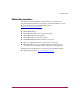
About this Guide About this Guide This guide provides information about installing an MSA1500, whether into an existing or new SAN, and is organized as follows: About this Guide ■ Chapter 1: Installation Procedures - All Deployments ■ Chapters 2-6: Configuration Procedures - for each Operating System To use this guide, follow all instructions in Chapter 1, and then proceed to the chapter for your specific operating system for some additional setup and configuration tasks.
About this Guide Prerequisites ■ Determine who will install and configure your MSA. A moderate knowledge level about SANs and their components is required to install this storage array system. If you are not familiar with installing and configuring storage array systems in a SAN, HP can install your MSA for you. For more information, see “Getting help” on page 13. ■ Complete the planning worksheet on the configuration overview poster.
About this Guide Related documentation The following (and other) MSA-related documents are available on the Documentation CD (included in the shipping carton with the MSA) or on the Technical documents page of the MSA1500 website: http://www.hp.com/go/msa1500cs.
About this Guide Document conventions The following document conventions apply in most cases.
About this Guide Note: Text set off in this manner presents commentary, sidelights, or interesting points of information. Equipment symbols The following equipment symbols may be found on hardware for which this guide pertains. They have the following meanings: Any enclosed surface or area of the equipment marked with these symbols indicates the presence of electrical shock hazards. Enclosed area contains no operator serviceable parts.
About this Guide Power supplies or systems marked with these symbols indicate the presence of multiple sources of power. WARNING: To reduce the risk of personal injury from electrical shock, remove all power cords to completely disconnect power from the power supplies and systems. Any product or assembly marked with these symbols indicates that the component exceeds the recommended weight for one individual to handle safely.
About this Guide Getting help If you have questions after reading this guide, contact an HP authorized service provider or access our website: http://www.hp.com. Note: HP call centers use product and serial numbers to validate warranty entitlement. Most HP products can provide product number, serial number and firmware revision electronically through the use of supplied management or diagnostic utilities, eliminating the need to physically inspect or remove products from installed enclosures.
About this Guide HP technical support Telephone numbers for worldwide technical support are listed on the following HP website: http://www.hp.com/support/. From this website, select the country of origin. Note: For continuous quality improvement, calls may be recorded or monitored.
Installation Procedures All Deployments 1 Installing and configuring your MSA includes the following steps, each of which is illustrated in Figure 1 and discussed in this chapter: ■ Step 1: Review and confirm your plans, page 17 ■ Step 2: Prepare your site, page 34 ■ Step 3: Install MSA option kits, page 36 ■ Step 4: Rack the MSA and the storage enclosures, page 37 ■ Step 5: Install the hard drives, page 43 ■ Step 6: Prepare your servers, page 44 ■ Step 7: Install the HBA in your servers, pag
Installation Procedures - All Deployments 1 2 8 ~A ~A ~B ~B 6 7 11 10 3 4 1 Review/confirm your plans 2 Prepare your site 3 Install MSA option kits 4 Rack the MSA 5 Install the hard drives 6 Prepare the servers 7 Install the HBAs 8 Prepare the switches 9 Connect the cables 10 Power on the devices 11 Configure the MSA 5 9 Figure 1: Overview of MSA installation procedures 16 HP StorageWorks 1500 Modular Smart Array Installation Guide
Installation Procedures - All Deployments Step 1: Review and confirm your plans Before installing the MSA, HP recommends thorough research and study to develop the best installation and configuration plan for your environment. Proper planning ensures a successful installation.
Installation Procedures - All Deployments Table 1: Basic MSA firmware and configuration options Firmware type active/passive version active/active version Number of controllers Single controller Configuration status Standard shipping configuration Supported Operating Systems Windows HP-UX Linux NetWare SCO VMware Dual controller Added hardware (controller and I/O module) Windows Linux NetWare VMware Single controller Not supported Not supported Dual controller Added hardware (controller and I/O
Installation Procedures - All Deployments Note: When examining the available firmware versions, consider the following: ■ The MSA ships with a single controller and active/passive firmware pre-installed. If you plan to install an additional MSA controller and are interested in upgrading to active/active, consider the complexity of your SAN, including the variety of device types, operating systems, failover tools, and access requirements.
Installation Procedures - All Deployments Complete the planning worksheet on the poster The printed configuration overview poster, included in the shipping carton, is a companion to this installation guide, and should be completed before installing your MSA.
Installation Procedures - All Deployments Go to the Internet for the most recent MSA and SAN information HP recommends going to the following websites to learn more about MSA devices and Storage Area Networks (SANs). Information found at these web sites may offer suggestions, alternatives, or changes to your installation plans. Table 2: MSA1500 and SAN-related websites website Content MSA1500 www.hp.
Installation Procedures - All Deployments Table 2: MSA1500 and SAN-related websites website Content HP Storage Management Initiative Specification provider for the MSA http://h18007.www1.hp.com/ support/files/storage/us/ download/23385.html Provides the Web-based management interface for the management of the MSA, in compliance with the SMI-S standard. This MSA-specific SMI-S provider can be installed on Microsoft Windows 2000 or Windows 2003 Server hosts with access to the MSA.
Installation Procedures - All Deployments Table 2: MSA1500 and SAN-related websites website Content HP MPIO Basic Failover http://h18006.www1.hp.com/ products/sanworks/ multipathoptions/index.html Multi-pathing software for Windows (active/passive environments only) Used in multi-pathing environments running active/passive array controller firmware, HP MPIO Basic Failover provides basic path failover and path recovery.
Installation Procedures - All Deployments Review MSA installation best practices ■ Before installing your MSA (and periodically afterwards), go to the MSA1500 website to confirm your installation plans and read current information about the device: http://www.hp.com/go/msa1500cs. ■ Periodically check the MSA website for firmware updates and other announcements. HP may place new versions of MSA controller firmware (or other support items) on the Web.
Installation Procedures - All Deployments — To provide redundant storage, configure your Logical Units (LUNs) using fault-tolerant Redundant Array of Independent Disks (RAID) levels and striping methods. Stripe the LUNs vertically across separate storage enclosures on different SCSI buses, including drives from each bus. — To provide redundant data paths, you must include two separate and isolated Fibre Channel fabrics and the associated hardware and software components in the configuration.
Installation Procedures - All Deployments ■ When planning and configuring the LUNs: — In direct-connect environments or any environment using the ACU-CLI, a minimum of one storage LUN on the MSA must be configured and set to the appropriate host mode before connecting the MSA to the server.
Installation Procedures - All Deployments ■ After configuring the LUNs, remember to: — Verify that all HBA connections to the MSA are recognized, including both paths in a multipath configuration. Each time the MSA is power-cycled, all active connections to the MSA are automatically detected and identified by their World Wide Port Name (WWPN). As needed, manually add the additional connections.
Installation Procedures - All Deployments — Manual load balancing—Through the ACU or the CLI, indicate the preferred path (controller ownership) for each LUN. This method is recommended for environments that are load balancing from the host. ■ In dual-controller multipath configurations (both active/active and active/passive), you must install some management software (such as multipathing software, management/monitoring utilities, and array configuration software) on each server with access to the MSA.
Installation Procedures - All Deployments If both controllers are operational and both need servicing, schedule a maintenance window and perform the service as for a single-controller configuration. If both controllers are operational and one needs servicing, do the following to disable and then service the controller: Note: The MSA operates in a non-redundant mode during this procedure. a. Access a supported management utility for the MSA. b. In the utility, disable the controller to be removed.
Installation Procedures - All Deployments Plan your storage configuration Proper planning of the system storage and its subsequent performance is critical to a successful deployment of your MSA. Improper planning or implementation can result in wasted storage space, degraded performance, or inability to expand the system to meet growing storage needs.
Installation Procedures - All Deployments Striping methods A storage array combines the capacity of several physical hard drives into one virtual unit called an array. These arrays are then presented to the operating system as a single disk device. The physical layout of an array can be one of two configurations: ■ Vertical striping—Offers ultimate fault tolerance and performance, but at the price of storage efficiency.
Installation Procedures - All Deployments Table 3: RAID level comparison RAID Level Alternative Name I/O Performance Fault Tolerance Storage Efficiency RAID 0 Data striping Highest None Highest RAID 1 Drive mirroring Data striping plus drive mirroring High * Highest * Low RAID 5 Data striping, with one set of distributed parity data Medium Medium High RAID 6 Data striping, with two sets of distributed parity data Low High Medium RAID 1+0 * Drives in the array need to be striped ac
Installation Procedures - All Deployments Spare drives HP recommends including spare drives in your LUNs. Spares are hard drives that are not active members of any particular LUN, but have been configured to be used in the event that a drive in one of the LUNs should fail. If a spare is present and a physical hard drive fails, the spare automatically replaces the failed drive as a member of the LUN and the process of rebuilding the information onto the spare automatically begins.
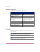
Installation Procedures - All Deployments Step 2: Prepare your site To ensure continuous, safe, and reliable operation of your equipment, place your system in an approved environment. You must provide adequate physical space, ventilation, and power. Note: Consider using the HP Enterprise Configurator (eCO) to help you plan and configure racks and rack-mountable devices. The eCO is available on the HP website: http://h30099.www3.hp.com/configurator.
Installation Procedures - All Deployments Table 4: MSA1500 specifications Parameter Value Dimensions: Height Width Depth 3.46 in (8.79 cm) 24.0 in (60.96 cm) 17.64 in (44.81 cm) Weight Shipping configuration 41.6 lb (18.9 kg) Input Power: Rated Input Voltage Rated Input Frequency Maximum Rated Input Current Maximum Input Power 100 to 240 VAC 47-63 Hz 1.
Installation Procedures - All Deployments Step 3: Install MSA option kits If your plans include adding any of the available option kits for the MSA, install them now. It is easier to install these options before racking the system. Some of the available option kits include: additional controller cache, additional SCSI I/O module, additional MSA controller, and additional Fibre Channel I/O module. Note: Remove blanking panels only for the options being installed.
Installation Procedures - All Deployments Step 4: Rack the MSA and the storage enclosures The MSA and its supported storage enclosures can be installed into most standard server racks. To verify that the rack and the storage enclosures you plan to use are supported for use with the MSA and its storage enclosures, read the compatibility guide, located on the Technical documents page of the MSA1500 website: http://www.hp.com/go/msa1500cs.
Installation Procedures - All Deployments Caution: To prevent damage and to ease insertion of the device into the rack, support the weight of the device and keep it level when sliding it into the rack. WARNING: To reduce the risk of personal injury or damage to the equipment, be sure that: ■ The leveling jacks on the rack are extended to the floor. ■ The full weight of the rack rests on the leveling jacks. ■ The stabilizing feet are attached to the rack if it is a single-rack installation.
Installation Procedures - All Deployments c. Use a pencil to mark the required location of the scissor-like locking latches on the rails, as indicated by the template. d. Repeat these steps to mark the back of the rack, using the information on the back of the template as a guide. 2. If the holes in the rack uprights are round instead of square, remove the standard pins from the rails and replace them with the round-hold pins provided with the rail kit. WARNING: The pins in the rails are load-bearing.
Installation Procedures - All Deployments c. Extend the back end of the rail toward the inside rear of the rack until the pins extend through the holes marked during the rack template procedure and the locking latch engages. d. Loosen the locking nut on the shipping retaining bracket and slide the bracket to the farthest position on the rear of the rail. 2 1 e. Repeat steps a through d for the left rack rail.
Installation Procedures - All Deployments 4. Install the component in the rack: a. Remove the bezel from the front of the device, align the device with the rails, and slide it into the rack. b. Slide the device into the rack until the front edge is flush with the front of the rack (1). c. Secure the device to the front of the rack using the provided thumbscrews on the front of the device (2) and then replace the front bezel.
Installation Procedures - All Deployments 5. Secure the device in the rack: a. Loosen the thumbscrew on the shipping retaining bracket (1) and slide the bracket forward (2) until the tab engages the slot in the chassis. 2 1 b. Tighten the thumbscrew on the bracket. c. Repeat these steps for the other rail.
Installation Procedures - All Deployments Step 5: Install the hard drives After the storage enclosures are secured in the rack, install the hard drives into the drive bays. For a list of supported hard drives, see the compatibility guide, located on the Technical documents page of the MSA1500 website: http://www.hp.com/go/msa1500cs. Caution: Follow industry-standard practices when handling hard drives.
Installation Procedures - All Deployments Step 6: Prepare your servers In an existing SAN, the servers are already set up and configured, but if you are deploying your MSA into a new SAN, install and configure your servers at this time. HP recommends that you: ■ Verify that the servers and operating systems you plan to use are supported for use with the MSA.
Installation Procedures - All Deployments Step 7: Install the HBA in your servers After you have confirmed that your servers are operating properly, install the HBA for the MSA in each server that will access the MSA. Because the MSA can be deployed into a variety of operating system environments and configurations (including single-path and multi-path), specific HBAs are required for the different deployments.
Installation Procedures - All Deployments Step 8: Prepare your switches In an existing SAN, your switches are already set up and configured, but if you are deploying your MSA into a new SAN, you need to install and configure your Fibre Channel switches at this time. Note: If you are connecting the Fibre Channel I/O module of the MSA directly to the HBA in the server, proceed to the next step. Direct connections are supported on Windows Server 2003 32-bit Enterprise Edition, Windows 2000, and HP-UX.
Installation Procedures - All Deployments Step 9: Connect the cables At this point in the process of installing your MSA, you have either installed your new SAN or prepared your existing SAN for the MSA, your server is ready, your switch is ready, and the MSA is ready. Now is the time for: ■ Connecting the SCSI cables ■ Connecting the Fibre Channel cables ■ Connecting the power cords Each of these connection types is discussed in the following paragraphs.
Installation Procedures - All Deployments Connecting the SCSI cables To connect the MSA to the storage enclosures, use standard VHDCI SCSI cables included in the shipping carton with each storage enclosure. Recommended SCSI cable connections HP recommends installing additional SCSI I/O modules and connecting storage enclosures in the same sequence as the pre-assigned box numbers, as illustrated in Figure 2.
Installation Procedures - All Deployments Supported and unsupported SCSI connections Each MSA SCSI I/O module has two ports — depending on the type of storage enclosure you plan to connect, one or both of the ports may be supported. See Table 5 for examples of supported and unsupported connections and see Figure 3 and Figure 4 for illustrations of sample configurations.
Installation Procedures - All Deployments Connecting the MSA to SATA storage enclosures The following illustration shows the MSA1500 connected to two MSA20 SATA storage enclosures. Note: Tighten the thumbscrews on the SCSI cables to ensure a secure connection.
Installation Procedures - All Deployments Connecting the MSA to SCSI storage enclosures The following illustration shows the MSA1500 connected to one dual-bus MSA30 SCSI storage enclosure. Note: Tighten the thumbscrews on the SCSI cables to ensure a secure connection.
Installation Procedures - All Deployments Connecting the Fibre Channel cables Your MSA can be deployed into a variety of configurations, from relatively simple single-path configurations to more complex multi-path configurations. Because there are two switches, two HBAs, and two servers in multi-path configurations, all of which use Fibre Channel cables, cable connections must follow specific installation requirements.
Installation Procedures - All Deployments Connecting Fibre Channel cables in a single-path configuration Figure 5 shows the Fibre Channel cable connections of an MSA1500 being accessed by two servers in a single-path configuration.
Installation Procedures - All Deployments Connecting Fibre Channel cables in a multi-path configuration Figure 6 shows the Fibre Channel cable connections of an MSA1500 being accessed by two servers, but in a multi-path configuration.
Installation Procedures - All Deployments Connecting the power cords To protect your system from power-failure-related down time, each MSA ships standard with a redundant power supply. Depending how you connect the power supplies to your power source, you can eliminate down time caused by power-related failures. When connecting the power cords, use the power cords shipped with the MSA.
Installation Procedures - All Deployments WARNING: To reduce the risk of electric shock or damage to the equipment: ■ Do not disable the power cord grounding plug. The grounding plug is an important safety feature. ■ Plug the power cord into a grounded (earthed) electrical outlet that is easily accessible at all times. ■ To remove power to the equipment, unplug the power cord from the power supply. ■ Route the power cord so that it is not likely to be walked on or pinched by items placed against it.
Installation Procedures - All Deployments Step 10: Power on the devices After the MSA and its storage enclosures are installed and connected to the SAN, power up all of the devices in the SAN and verify that they are operating properly. 1. Apply power to each UPS. 2. Apply power to each external Fibre Channel switch. 3. Apply power to each attached storage enclosure. 4. Power on the MSA by pressing the power/standby button on the front panel.
Installation Procedures - All Deployments Caution: When you power on the server, the monitor may display a “New Hardware Found” message and prompt to install an HBA driver. Cancel out of this window to prevent the installation of an unsupported HBA driver. 8. Verify that each component in the SAN is operating properly.
Installation Procedures - All Deployments Read the messages on the controller display panel Each controller contains an integrated LCD panel. This panel displays informational and error messages, shows the current status of the MSA, and provides an interface for user input.
Installation Procedures - All Deployments Verify the operating status of the storage enclosures To verify that your storage enclosures and hard drives are operating properly, view the enclosure and hard drive LEDs and compare them with the patterns described in the documentation for these devices. If the LEDs indicate a fault, refer to the documentation that came with the enclosure for help.
Installation Procedures - All Deployments Step 11: Configure your MSA After the servers and switches are set up and the MSA is physically installed, connected, and powered on, you may customize the server and the MSA and configure the storage according to your plan.
Installation Procedures - All Deployments 7. Scroll through and read the display for the Web versions of the Support Software CD and MSA controller firmware, and then record the version numbers in Table 10: “MSA1500 Information” on page 108. 8. If desired, download the updated firmware or support software CD ISO image from the web. Note: When instructed in later sections of this guide, install this new firmware on the MSA and use this new Support CD.
Installation Procedures - All Deployments About the Array Configuration Utility The Array Configuration Utility (ACU) is a server-based, browser-accessed tool used to configure an array controller and its storage. The ACU is supported for use in Windows, Linux, and NetWare environments and can run locally from the server or remotely through HP Systems Insight Manager (HP-SIM). The ACU: ■ Provides a graphical user interface view of HP array configurations. ■ Includes easy to use configuration wizards.
Installation Procedures - All Deployments About the Array Configuration Utility - Command Line Interface The Array Configuration Utility - Command Line Interface (ACU-CLI) is a command line user interface that can run locally through your browser or remotely through HP Insight Manager. The ACU is supported for use in Windows, Linux, NetWare, and HP-UX environments and can run locally from the server or remotely through HP Systems Insight Manager (HP-SIM).
Installation Procedures - All Deployments Configure the MSA To configure your MSA, go to the chapter for your specific operating system: ■ Chapter 2: Configuration Procedures - Windows Environments, page 67 ■ Chapter 3: Configuration Procedures - Linux Environments, page 73 ■ Chapter 4: Configuration Procedures - HP-UX Environments, page 81 ■ Chapter 5: Configuration Procedures - OpenVMS Environments, page 87 ■ Chapter 6: Configuration Procedures - Other Environments, page 93 HP StorageWorks 1500
Installation Procedures - All Deployments 66 HP StorageWorks 1500 Modular Smart Array Installation Guide
Configuration Procedures Windows Environments 2 Deploying the MSA in a Microsoft Windows environment involves: 1. Completing all Prerequisites, page 67 2. Installing MSA-specific components on the servers, page 68 3. Updating MSA controller firmware (if necessary), page 71 4. Configuring the storage, page 72 Each of these procedures is discussed in the following paragraphs. Note: HP recommends installing your MSA in the sequence of steps listed here and in chapter 1 of this guide.
Configuration Procedures - Windows Environments Installing MSA-specific components on the servers Because these installation processes involve updating the server configuration, HP recommends performing these tasks during inactive periods. MSA-specific components include: ■ HBA drivers ■ Array Configuration Utility (ACU) ■ Array Configuration Utility-Command Line Interface (ACU-CLI) (The ACU-CLI is not supported on IA64 platforms.
Configuration Procedures - Windows Environments 3. When prompted, read and accept the license agreement. The Support Software CD main menu is displayed. 4. In the CD Main Menu, do the following: a. Click View Contents to review notes and information that supplement this document. Caution: Use only the MSA Support Software CD to install HBA drivers. Drivers for all supported HBAs are included on the CD and are the only versions approved for use with the MSA.
Configuration Procedures - Windows Environments b. Install the following component (required): — HBA driver (and the included Windows Event Notification Service) Important: After installing the HBA and Event Notification Service drivers, remove the Support Software CD from the CD-ROM drive and restart the server. Then, re-insert the MSA Support Software CD and access the CD main menu. c.
Configuration Procedures - Windows Environments Updating MSA controller firmware (if necessary) If you need to update the firmware on your MSA controller to a version downloaded from the MSA website, do so at this time.
Configuration Procedures - Windows Environments Configuring the storage Thorough planning is critical to the successful and efficient deployment of any storage array system. As discussed in Chapter 1: Installation Procedures All Deployments, page 15, plans should include decisions about total system capacity, fault-tolerance levels (availability), and performance.
Configuration Procedures Linux Environments 3 Deploying the MSA in a Linux environment involves: 1. Completing all Prerequisites, page 73 2. Installing MSA-specific components on the servers, page 74 3. Updating MSA controller firmware (if necessary), page 78 4. Configuring the storage, page 79 Each of these procedures is discussed in the following paragraphs. Note: HP recommends installing your MSA in the sequence of steps listed here and in chapter 1 of this guide.
Configuration Procedures - Linux Environments Installing MSA-specific components on the servers Because these installation processes involve updating the server configuration, HP recommends performing these tasks during inactive periods.
Configuration Procedures - Linux Environments 6. To install the HBA drivers: Caution: Use only the Support Software CD to install the HBA drivers. Drivers for all supported HBAs are included on the CD and are the only versions approved for use with the MSA. a. Navigate to the /RDP/Linux/ directory on the CD. b. List the contents of the directory and navigate to either the Emulex or QLogic directory, depending on the maker of your HBA. c.
Configuration Procedures - Linux Environments e. Install the System Management Homepage by entering: rpm -ivh (Where is the name of the System Management Homepage rpm.) 8. To install the Array Configuration Utility (ACU): Note: ■ You must remove earlier versions of the ACU before installing later versions. ■ You must install the HP System Management Homepage before installing the ACU.
Configuration Procedures - Linux Environments d. Install the ACU-CLI by entering: rpm -ivh (Where is the name of the ACU-CLI rpm.) 10. After all desired components are installed, remove the Support Software CD from the CD-ROM drive. 11. Restart the server. 12. Repeat these procedures for each Linux server that will access the MSA.
Configuration Procedures - Linux Environments Updating MSA controller firmware (if necessary) If you need to update the firmware on your MSA controller to a version downloaded from the MSA1500 website, do so at this time.
Configuration Procedures - Linux Environments Configuring the storage Thorough planning is critical to the successful and efficient deployment of any storage array system. As discussed in Chapter 1: “Installation Procedures All Deployments” on page 15, plans should include decisions about total system capacity, fault-tolerance, performance, and availability. Although detailed in the ACU and the CLI user guides, basic configuration tasks include (in the following sequence): ■ Creating the arrays (LUNs).
Configuration Procedures - Linux Environments 80 HP StorageWorks 1500 Modular Smart Array Installation Guide
Configuration Procedures HP-UX Environments 4 Deploying the MSA in an HP-UX environment involves: 1. Completing all Prerequisites, page 81 2. Reading the Additional HP-UX support notes, page 82 3. Installing the ACU-CLI on the servers (optional), page 84 4. Updating MSA controller firmware (if necessary), page 85 5. Configuring the storage, page 86 Each of these procedures is discussed in the following paragraphs.
Configuration Procedures - HP-UX Environments Additional HP-UX support notes ■ Supported HP-UX operating system versions: — HP-UX 11i v1(PA) — HP-UX 11i v2(PA/IA) ■ Supported controller configurations: — Single controller (active/passive firmware only) — Dual controllers (active/active firmware only) ■ Supported Fibre Channel connections: — Fabric connection to an external switch — Direct connection to the HBA in the server (Limitations may exist.
Configuration Procedures - HP-UX Environments HP-UX version Required update for active/active 11.11 systems HWE0509 Online Diagnostics Support Tools Bundle, Sept. 2005 (or later) 11.23 systems HWE0603 Online Diagnostics Support Tools Bundle, June 2006 (or later) These bundles are available on the HP Software Depot home website: http://h20293.www2.hp.com.
Configuration Procedures - HP-UX Environments Installing the ACU-CLI on the servers (optional) To use the ACU-CLI to configure MSA storage, perform the following steps to install it on the servers: Note: ■ You must remove earlier versions of the ACU before installing later versions. ■ For information about using the ACU-CLI, see ACU-CLI online help, the HP-UX ACU-CLI readme file or release notes, or the HP Configuring Arrays Reference Guide. 1.
Configuration Procedures - HP-UX Environments Updating MSA controller firmware (if necessary) If you need to update the firmware on your MSA controller to a version downloaded from the MSA1500 website, do so at this time.
Configuration Procedures - HP-UX Environments Configuring the storage Thorough planning is critical to the successful and efficient deployment of any storage array system. As discussed in Chapter 1: “Installation Procedures All Deployments” on page 15, plans should include decisions about total system capacity, fault-tolerance levels (availability), and performance.
Configuration Procedures OpenVMS Environments 5 Deploying the MSA in an OpenVMS environment involves: 1. Completing all Prerequisites, page 87 2. Obtaining World Wide Port Names, page 88 3. Installing the current Fibre_SCSI patch on the servers, page 89 4. Updating MSA controller firmware (if necessary), page 90 5. Configuring the storage, page 91 6. Assigning ID Numbers to the Controllers and LUNs, page 92 Each of these procedures is discussed in the following paragraphs.
Configuration Procedures - OpenVMS Environments Obtaining World Wide Port Names When setting connections to the MSA, you must supply the WWPNs of the Fibre Channel adapters on the OpenVMS system. To obtain the WWPNs: 1. From OpenVMS, use the following DCL command: $ show device fg/full The following information is displayed: Device FGA0: device type KGPSA Fibre Channel, is online, shareable, error logging is enabled.
Configuration Procedures - OpenVMS Environments Installing the current Fibre_SCSI patch on the servers 1. Download the current patch from the HP OpenVMS Systems website: http://h71000.www7.hp.com/serv_support.html. a. Navigate to the HP Proactive service tools banner. b. Select one of the following options: — Register to access the HP Patch Database — FTP site for OpenVMS patches c. Follow the onscreen instructions to navigate to and download the patch.
Configuration Procedures - OpenVMS Environments Updating MSA controller firmware (if necessary) If you need to update the firmware on your MSA controller to a version downloaded from the MSA1500 website, do so at this time.
Configuration Procedures - OpenVMS Environments Configuring the storage Thorough planning is critical to the successful and efficient deployment of any storage array system. As discussed in Chapter 1: “Installation Procedures All Deployments” on page 15, plans should include decisions about total system capacity, fault-tolerance levels (availability), and performance.
Configuration Procedures - OpenVMS Environments Assigning ID Numbers to the Controllers and LUNs When configuring your MSA, you must assign a unique ID number to each MSA controller and to each MSA storage LUN. See the HP StorageWorks 1000/1500 Command Line Interface reference guide for specific instructions.
Configuration Procedures Other Environments 6 Deploying the MSA in a NetWare, Tru64 UNIX, SCO UNIX, or VMware operating system environment involves: 1. Completing all Prerequisites, page 93 2. Updating MSA controller firmware (if necessary), page 97 3. Configuring the storage, page 98 Each of these procedures is discussed in the following paragraphs. Note: HP recommends installing your MSA in the sequence of steps listed here and in chapter 1 of this guide.
Configuration Procedures - Other Environments Operating-system-specific notes Note: SCO UNIX, VMWare, OpenVMS, and Tru64 UNIX do not use the provided MSA Support Software CD. These operating systems use the MSA-CLI to configure the storage and obtain the HBA drivers and multipathing tools from a different source, such as through operating system updates or the HP website. NetWare environments ■ Single-controller configurations are supported for use with active/passive firmware only.
Configuration Procedures - Other Environments d. For each HBA, verify that the following options are specified: load ql2x00.ham slot=x/luns/allpaths/portnames, where x represents the slot number. Note: The Native MPIO solution can co-exist with HP Secure Path for NetWare. ■ If the MSA is upgraded to 6.86or later active/active firmware, and, if you want to remove the Secure Path for NetWare driver, do the following: a. Follow the removal instructions provided in the Secure Path user documents. b.
Configuration Procedures - Other Environments SCO UNIX environments ■ Dual-controller active/passive configurations are not supported. Dual-controller configurations must run active/active firmware. ■ Detailed information about deploying an MSA in a SCO UNIX environment is provided in a separate document on the MSA1500 Technical Documents web page. Included in the SCO-specific document are the procedures for obtaining and installing the HBA drivers for each SCO UNIX operating system.
Configuration Procedures - Other Environments Updating MSA controller firmware (if necessary) If you need to update the firmware on your MSA controller to a version downloaded from the web, do so at this time.
Configuration Procedures - Other Environments Configuring the storage Thorough planning is critical to the successful and efficient deployment of any storage array system. As discussed in Chapter 1: “Installation Procedures All Deployments” on page 15, plans should include decisions about total system capacity, fault-tolerance levels (availability), and performance.
Regulatory Notices A Regulatory Compliance identification numbers For the purpose of regulatory compliance certifications and identification, your device is assigned an HP Series number. The Series number can be found on the product label, along with the required approval markings and information. The product label is located on the right side of the chassis. When requesting certification information for this product, always refer to this Series number.
Regulatory Notices Canadian notice (Avis Canadien) This Class A digital apparatus meets all requirements of the Canadian Interference-Causing Equipment Regulations. Cet appareil numérique de la classe A respecte toutes les exigences du Règlement sur le matériel brouilleur du Canada. European Union notice Products with the CE Marking comply with both the EMC Directive (89/336/EEC) and the Low Voltage Directive (73/23/EEC) issued by the Commission of the European Community.
Regulatory Notices Japanese power cord notice BSMI notice Laser compliance The SFP Module contains a laser diode of gallium aluminum arsenide (GaALAs) emitting in the wavelength range of 770-860 nm or indium gallium arsenide phosphide (InGaAsP) emitting in the wavelength range of 1270-1355 nm. All HP systems equipped with a laser device comply with safety standards, including International Electrotechnical Commission (IEC) 825.
Regulatory Notices The Center for Devices and Radiological Health (CDRH) of the U.S. Food and Drug Administration implemented regulations for laser products on August 2, 1976. These regulations apply to laser products manufactured from August 1, 1976. Compliance is mandatory for products marketed in the United States. This device is classified as a Class 1 laser product as defined by IEC 825. This indicates that the product is classified as a CLASS 1 LASER PRODUCT.
Regulatory Notices Disposal of waste equipment by users in private households in the European Union This symbol on the product or on its packaging indicates that this product must not be disposed of with your other household waste. Instead, it is your responsibility to dispose of your waste equipment by handing it over to a designated collection point for the recycling of waste electrical and electronic equipment.
Regulatory Notices 104 HP StorageWorks 1500 Modular Smart Array Installation Guide
Electrostatic Discharge B To prevent damage to the system, be aware of the precautions you need to follow when setting up the system or handling parts. A discharge of static electricity from a finger or other conductor may damage system boards or other static-sensitive devices. This type of damage may reduce the life expectancy of the device. Prevention methods ■ Avoid hand contact by transporting and storing products in static-safe containers.
Electrostatic Discharge Grounding methods There are several methods for grounding. Use one or more of the following methods when handling or installing electrostatic-sensitive parts: ■ Use a wrist strap connected by a ground cord to a grounded workstation or computer chassis. Wrist straps are flexible straps with a minimum of 1 megohm ± 10 percent resistance in the ground cords. To provide proper ground, wear the strap snug against the skin.
Worksheets C Use these worksheets to record information about your MSA. Note: Although these worksheets are not prerequisites for installing your MSA, some of the information is required for multi-pathing, future configuration changes, and troubleshooting purposes.
Worksheets Table 10: MSA1500 Information Component Setting ❑ Single-path, non-clustered ❑ Single-path, clustered-servers ❑ Multi-path, non-clustered ❑ Multi-path, multiple clustered-servers Configuration Type (check one) MSA1500 Serial number (on the product label) Controller firmware: Version shipped on the controller ____________________________________ ____________________________________ ____________________________________ Version available on the Web Support Software CD: Version shipped with th
Worksheets Table 11: External Fibre Channel Interconnect Device (Switch) Information Component Setting Primary Switch Make and model Switch firmware version Switch IP Address Switch WWNN Switch WWPN Additional Device for Multi-Path Configurations: Make and model Switch firmware version Switch IP Address Switch WWNN Switch WWPN ____________________________________ ____________________________________ ____________________________________ ____________________________________ _______________________________
Worksheets Table 12: Server Information Component Setting Primary Server Make and model Operating system and version / kernel Service pack / Errata Server name HBA model HBA server slot location HBA firmware version HBA driver version HBA boot BIOS firmware HBA WWNN HBA WWPN (also called Adapter ID) ____________________________________ ____________________________________ ____________________________________ ____________________________________ ____________________________________ ______________________
Worksheets Table 12: Server Information Component Setting Additional Server Make and model Operating system and version / kernel Service pack / Errata Server name HBA model HBA server slot location HBA firmware version HBA driver version HBA boot BIOS firmware HBA WWNN HBA WWPN (also called Adapter ID): ____________________________________ ____________________________________ ____________________________________ ____________________________________ ____________________________________ __________________
Worksheets Table 12: Server Information Component Setting Additional Server Make and model Operating system and version / kernel Service pack / Errata Server name HBA model HBA server slot location HBA firmware version HBA driver version HBA boot BIOS firmware HBA WWNN HBA WWPN (also called Adapter ID) ____________________________________ ____________________________________ ____________________________________ ____________________________________ ____________________________________ ___________________
Worksheets Table 12: Server Information Component Setting Additional Server Make and model Operating system and version / kernel Service pack / Errata Server name HBA model HBA server slot location HBA firmware version HBA driver version HBA boot BIOS firmware HBA WWNN HBA WWPN (also called Adapter ID) ____________________________________ ____________________________________ ____________________________________ ____________________________________ ____________________________________ ___________________
Worksheets Table 13: Hard Drive Information Box Number Drive Bay Transfer Rate Drive Capacity Spindle Speed Array Letter (LUN #) 1 2 3 Box Number Assigned to this Enclosure ________ 4 5 6 7 8 9 10 11 12 13 14 Note: Recording information about the hard drives and their configuration is a two-step process: ■ As you install the hard drives, record basic information about the drives in this table.
Worksheets Table 13: Hard Drive Information Box Number Drive Bay Transfer Rate Drive Capacity Spindle Speed Array Letter (LUN #) 1 2 3 Box Number Assigned to this Enclosure ________ 4 5 6 7 8 9 10 11 12 13 14 Note: Box numbers are assigned to enclosures based on their connection to the MSA1500. See Figure 2 “SCSI I/O modules, bus numbers, and box numbers” on page 48 for the box number assignment pattern.
Worksheets Table 13: Hard Drive Information Box Number Drive Bay Transfer Rate Drive Capacity Spindle Speed Array Letter (LUN #) 1 2 3 Box Number Assigned to this Enclosure ________ 4 5 6 7 8 9 10 11 12 13 14 116 HP StorageWorks 1500 Modular Smart Array Installation Guide
Worksheets Table 13: Hard Drive Information Box Number Drive Bay Transfer Rate Drive Capacity Spindle Speed Array Letter (LUN #) 1 2 3 Box Number Assigned to this Enclosure ________ 4 5 6 7 8 9 10 11 12 13 14 HP StorageWorks 1500 Modular Smart Array Installation Guide 117
Worksheets Table 14: Array (LUN) Information Basic Settings Array Letter (LUN #) 118 Capacity SSP (ACL) Settings RAID Level HBA WWPN or Name Host Mode (Profile) O/S Share Name HP StorageWorks 1500 Modular Smart Array Installation Guide
Worksheets Table 14: Array (LUN) Information Basic Settings Array Letter (LUN #) Capacity SSP (ACL) Settings RAID Level HBA WWPN or Name HP StorageWorks 1500 Modular Smart Array Installation Guide Host Mode (Profile) O/S Share Name 119
Worksheets Table 14: Array (LUN) Information Basic Settings Array Letter (LUN #) 120 Capacity SSP (ACL) Settings RAID Level HBA WWPN or Name Host Mode (Profile) O/S Share Name HP StorageWorks 1500 Modular Smart Array Installation Guide
Index B battery replacement notice 102 best practices cabling 47 general 24 racking 37 SCSI cable connections 48 box number assignments 48 bus number assignments 48 C cables best practices 47 Index Array Configuration Utility - Command Line Interface (ACU-CLI) information about 64 installing HP-UX environments 84 Linux environments 76 Windows environments 70 supported operating systems 64 Array Configuration Utility (ACU) information about 63 installing Linux environments 76 Windows environments 70 supp
Index E electrostatic discharge 105 enclosures bus and box numbers 48 installing 37 environmental, requirements 34 equipment symbols 11 F FCC notice 99 fibre cables, connecting 52 firmware cloning in dual-controller configurations 57 determining which version to use 17 updating in HP-UX environments 85 in Linux environments 78 in OpenVMS environments 90 in other environments 97 in Windows environments 71 G getting help 14 grounding methods 106 H hard drives approved models 43 installing 43 recommendatio
Index L LCD messages at MSA startup 59 LEDs of the MSA 58 Linux environments configuring the storage 79 installing the ACU 76 installing the ACU-CLI 76 installing the HBA driver 74 installing the System Management Home page 75 prerequisites for the MSA 73 updating MSA firmware 78 LUNs configuration planning 30 sizing considerations 33 M management server best practices 25 definition of 25 management software 25 messages, LCD at MSA startup 59 N NetWare environments configuration procedures 93 using the s
Index installing 39 RAID levels 31 recommendations MSA best practices 24 power sources 55 redundant controller note 36 fiber cables 52 power cables 55 redundant configurations notes about 57 regulatory compliance country notices 100 identification numbers 99 S SAN Infrastructure web site 21 SCO UNIX environments configuration procedures 93 SCSI cables, connecting 48 SCSI connections, supported and unsupported 49 SCSI I/O module, installing 36 Secure Path website 21 securing the system to the rack 41 serve
Index Tru64 UNIX environments configuration procedures 93 U updating MSA firmware determining which version to use 17 HP-UX environments 85 Linux environments 78 OpenVMS environments 90 other environments 97 Windows environments 71 V ventilation requirements 34 verifying the status of servers 60 of storage enclosures 60 of switches 60 of the MSA 59 W warnings power related 56 rack stability 12 symbols on equipment 11 websites HP storage 14 MSA and SAN 21 weight considerations 34 Windows environments co
Index 126 HP StorageWorks 1500 Modular Smart Array Installation Guide