HP StorageWorks 1500 Modular Smart Array installation guide Product Version: Controller firmware 5.xx or earlier, with active/passive support Controller firmware 7.0 or later, with active/active support This document details procedures for installing an HP StorageWorks 1500 Modular Smart Array controller shelf (MSA1500) and its attached storage enclosures. This guide is a companion to the MSA1500 Installation Overview poster.
Legal and notice information © Copyright 2004-2007 Hewlett-Packard Development Company, L.P. Hewlett-Packard Company makes no warranty of any kind with regard to this material, including, but not limited to, the implied warranties of merchantability and fitness for a particular purpose. Hewlett-Packard shall not be liable for errors contained herein or for incidental or consequential damages in connection with the furnishing, performance, or use of this material.
Contents About this guide . . . . . . . . . . . . . . . Contents .................................. 7 Intended audience . . . . . . . . . . . . . . . . . . . . . . . . . . . . . . . . . . . . . . . . . . . . . . . . . . . . . . . . . 7 Prerequisites . . . . . . . . . . . . . . . . . . . . . . . . . . . . . . . . . . . . . . . . . . . . . . . . . . . . . . . . . . . . . 8 Related documentation . . . . . . . . . . . . . . . . . . . . . . . . . . . . . . . . . . . . . . . . . . . . . . . . . . . . . .
Recommended SCSI cable connections . . . . . . . . . . . . . . . . . . . . . . . . . . . . . . . . . . . . . Supported and unsupported SCSI connections . . . . . . . . . . . . . . . . . . . . . . . . . . . . . . . . Connecting the MSA to SATA storage enclosures . . . . . . . . . . . . . . . . . . . . . . . . . . . . . . Connecting the MSA to SCSI storage enclosures. . . . . . . . . . . . . . . . . . . . . . . . . . . . . . . Connecting the Fibre Channel cables . . . . . . . . . . . . . . . . . . . . . . . .
Assigning ID Numbers to the controllers and LUNs . . . . . . . . . . . . . . . . . . . . . . . . . . . . . . . . . . 83 6 Configuration procedures—VMware environments . . . . . . . . . . . . . . . . . . . . . . 85 Prerequisites . . . . . . . . . . . . . . . . . . . . . . . . . . Updating MSA controller firmware (if necessary) . VMware-specific tasks . . . . . . . . . . . . . . . . . . . . Configuring the storage. . . . . . . . . . . . . . . . . . . . . . . . . . . . . . . . . . . . . . . . . . . . .
Figures 1 2 3 4 5 6 7 Tables 1 2 3 4 5 6 7 8 9 10 11 12 13 14 15 16 6 Overview of MSA installation procedures . . . . . . . . . . . . . . . . . . . . . . . . . . . SCSI I/O modules, bus numbers, and box numbers . . . . . . . . . . . . . . . . . . . . SCSI cable connections to two MSA20 SATA storage enclosures. . . . . . . . . . . SCSI cable connections to one MSA30 SCSI storage enclosure . . . . . . . . . . . . Sample Fibre Channel cable connections, singlepath configuration . . . . . . . . .
About this guide This guide provides information about installing an MSA1500 whether into an existing or new SAN, and is organized as follows: • Chapter 1: Installation procedures—All deployments • Chapters 2-6: Configuration procedures for each operating system To use this guide, follow all instructions in Chapter 1, and then proceed to the chapter for your specific operating system for some additional setup and configuration tasks.
Prerequisites Prerequisites for installing this product include: • Determine who will install and configure your MSA. A moderate knowledge level about SANs and their components is required to install this storage array system. If you are not familiar with installing and configuring storage array systems in a SAN, HP can install your MSA for you. For more information, see ”Intended audience” on page 7. • Complete the planning worksheet on the installation and configuration overview poster.
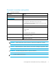
Document conventions and symbols Document conventions Table 1 Convention Element Medium blue text: Figure 1 Cross-reference links and e-mail addresses Medium blue, underlined text (http://www.hp.
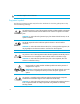
TIP: Provides helpful hints and shortcuts. Equipment symbols The following equipment symbols may be found on hardware for which this guide pertains. They have the following meanings: Any enclosed surface or area of the equipment marked with these symbols indicates the presence of electrical shock hazards. Enclosed area contains no operator serviceable parts. WARNING: To reduce the risk of personal injury from electrical shock hazards, do not open this enclosure.
Rack stability WARNING! To reduce the risk of personal injury or damage to equipment: • Extend leveling jacks to the floor. • Ensure that the full weight of the rack rests on the leveling jacks. • Install stabilizing feet on the rack. • In multiple-rack installations, secure racks together. • Extend only one rack component at a time. Racks may become unstable if more than one component is extended.
HP-authorized reseller For the name of your nearest HP-authorized reseller: • In the United States, call 1-800-345-1518. • Elsewhere, see the HP website: http://www.hp.com. Click Contact HP to find locations and telephone numbers. Helpful websites For third-party product information, see the following HP websites: • http://www.hp.com • http://www.hp.com/go/storage • http://www.hp.com/support/ • http://www.docs.hp.
1 Installation procedures—All deployments Installing and configuring your MSA includes the following steps, each of which is illustrated in Figure 1 and discussed in this chapter: • Step 1: Review and confirm your plans, page 15 • Step 2: Prepare your site, page 28 • Step 3: Install MSA option kits, page 30 • Step 4: Rack the MSA and the storage enclosures, page 31 • Step 5: Install the hard drives, page 36 • Step 6: Prepare your servers, page 37 • Step 7: Install the HBA in your servers, page 38 • Step 8:
1 1 Review/confirm your plans 2 2 Prepare your site 8 ~A ~A ~B ~B 6 7 11 3 Install MSA option kits 4 Rack the MSA 5 Install the hard drives 6 Prepare the servers 7 Install the HBAs 8 Prepare the switches 10 3 4 9 Connect the cables 10 Power on the devices 11 Configure the MSA 5 9 Figure 1: Overview of MSA installation procedures 14 Installation procedures—All deployments
Step 1: Review and confirm your plans Before installing the MSA, HP recommends thorough research and study to develop the best installation and configuration plan for your environment. Proper planning ensures a successful installation.
Table 2 Basic MSA firmware and configuration options Firmware type Number of controllers Configuration status Supported operating systems Windows active/passive version Single controller Standard shipping configuration HP-UX Linux NetWare SCO VMware Windows Dual controller Added hardware (controller and I/O module) Linux NetWare VMware active/active version Single controller Not supported Not supported Windows Dual controller Added hardware (controller and I/O module) and upgraded firmware
NOTE: When examining the available firmware versions, consider the following: • The MSA ships with a single controller and active/passive firmware pre-installed. If you plan to install an additional MSA controller and are interested in upgrading to active/active, consider the complexity of your SAN, including the variety of device types, operating systems, failover tools, and access requirements.
Go to the Internet for the most recent MSA and SAN information HP recommends going to the following websites to learn more about MSA devices and Storage Area Networks (SANs). Information found at these websites may offer suggestions, alternatives, or changes to your installation plans. Table 3 MSA1500 and SAN-related websites Website Content MSA1500 Latest MSA1500 information, including: • http://www.hp.
Table 3 MSA1500 and SAN-related websites (continued) Website Content HP Storage Management Initiative Specification provider for the MSA Provides the Web-based management interface for the management of the MSA, in compliance with the SMI-S standard. http://h18007.www1.hp.com/ support/files/storage/us/ download/23385.html This MSA-specific SMI-S provider can be installed on Microsoft Windows 2000 or Windows 2003 Server hosts with access to the MSA.
Table 3 MSA1500 and SAN-related websites (continued) Website Content QLogic Driver for HBA Control and Multipathing Multipathing tool for Linux (active/passive and active/active environments) http://h18006.www1.hp.com/ products/sanworks/ multipathoptions/index.html Emulex MultiPulse Path Failover for Linux Used in multipathing environments running either active/passive or active/active firmware, QLogic Driver for HBA Control and Multipathing provides multipathing support for Linux environments.
Review MSA installation best practices MSA installation best practices fall into one of three categories: planning, installation, and ongoing. Planning • Before installing your MSA (and periodically afterwards), go to the MSA1500 website to confirm your installation plans and read current information about the device: http://www.hp.com/go/msa1500cs. • Prepare for the installation by reviewing the Configuration Installation and Overview poster.
• When handling hard drives, follow industry-standard practices. Internal storage media can be damaged when drives are shaken, dropped, or roughly placed on a work surface. When removing a drive, press the release button, and then pull the drive only slightly out of the enclosure. Then, to allow time for the internal disk to stop rotating, wait approximately 10 seconds before completely removing the drive from the enclosure.
• Customize the RAID level and striping method to the type of data that will be stored on the LUN. For example, depending on the number of drives included in an array, the ACU may suggest RAID 6 (ADG) as the default RAID level, which offers a high level of fault tolerance and usable disk capacity, but at a significant cost to I/O performance. For comparable fault tolerance but higher performance, consider using RAID 1+0 when fault tolerance is desired and performance is more important than usable capacity.
Ongoing • Periodically check the MSA website for firmware updates and other announcements. HP may place new versions of MSA controller firmware (or other support items) on the Web. Updates include fixes to known issues, support for new features, and enhancements of existing features. For more information, see the MSA1000/1500 firmware updating guide, available on the Technical documentation page of the MSA1500 website: http://www.hp.com/go/msa1500cs.
b. In the utility, disable the controller to be removed. For details, see the utility online help or MSA user documentation. c. Wait for array controller disabled to display on the controller LCD panel. d. Remove the disabled controller for servicing or replacement. CAUTION: If an operational controller is removed without first being disabled, the active controller might halt. To clear this fault condition, you must power-cycle the MSA.
• Vertical striping—Offers ultimate fault tolerance and performance, but at the price of storage efficiency. • Horizontal striping—Allows for the creation of large arrays and efficient use of storage capacity, but at the price of I/O performance and less fault tolerance. In a vertical configuration, an array uses hard drives from separate storage enclosures and different SCSI buses. In a horizontal configuration, the array uses multiple drives contained within the same storage enclosure.
NOTE: For detailed information about the different RAID levels, see the HP Array Configuration Utility User Guide. This guide is available on the Documentation CD and on the Technical documentation page of the MSA1500 website: http://www.hp.com/go/msa1500cs. Hard drive sizes and types Hard drives in each enclosure and included in the same array should be the same size and type.
Step 2: Prepare your site To ensure continuous, safe, and reliable operation of your equipment, place your system in an approved environment. You must provide adequate physical space, ventilation, and power. NOTE: Consider using the HP Enterprise Configurator (eCO) to help you plan and configure racks and rack-mountable devices. The eCO is available on the HP website: http://h30099.www3.hp.com/configurator.
Table 5 MSA1500 specifications Parameter Value Dimensions: Height Width Depth 3.46 in. (8.79 cm) 24.0 in. (60.96 cm) 17.64 in. (44.81 cm) Weight Shipping configuration 41.6 lb (18.9 kg) Input power: Rated input voltage Rated input frequency Maximum rated input current Maximum input power Heat dissipation (max.) 100 to 240 VAC 47-63 Hz 1.3 A 160 W* 2187 Btu/hr* Temperature ranges: Operating temperature 50° F to 95° F (10° C to 35° C) [derated 1.8° F (1° C) per 1000 ft (304.
Step 3: Install MSA option kits If your plans include adding any of the available option kits for the MSA, install them now. It is easier to install these options before racking the system. Some of the available option kits include: additional controller cache, additional SCSI I/O module, additional MSA controller, and additional Fibre Channel I/O module. NOTE: Remove blanking panels only for the options being installed.
Step 4: Rack the MSA and the storage enclosures The MSA and its supported storage enclosures can be installed into most standard server racks. To verify that the rack and the storage enclosures you plan to use are supported for use with the MSA and its storage enclosures, read the compatibility guide, located on the Technical documentation page of the MSA1500 website: http://www.hp.com/go/msa1500cs.
WARNING! To reduce the risk of personal injury or damage to the equipment, be sure that: • The leveling jacks on the rack are extended to the floor. • The full weight of the rack rests on the leveling jacks. • The stabilizing feet are attached to the rack if it is a single-rack installation. • The racks are coupled together in multiple-rack installations. • Only one component in a rack is extended at a time. A rack may become unstable if more than one component is extended.
3. Install the rails in the rack: a. Identify the left (L) and right (R) rack rails by markings stamped into the rails. b. Insert the front end of the right rack rail into the inside front of the rack until the pins extend through the holes marked during the rack template procedure. NOTE: Be sure that the scissor-type locking latch engages when the end of the rail seats into the rack uprights. c.
d. Loosen the locking nut on the shipping retaining bracket and slide the bracket to the farthest position on the rear of the rail. 2 1 e. Repeat steps a through d for the left rack rail. 4. Install the component in the rack: a. Remove the bezel from the front of the device, align the device with the rails, and slide it into the rack.
b. Slide the device into the rack until the front edge is flush with the front of the rack (1). c. Secure the device to the front of the rack using the provided thumbscrews on the front of the device (2) and then replace the front bezel. 2 1 5. Secure the device in the rack: a. Loosen the thumbscrew on the shipping retaining bracket (1) and slide the bracket forward (2) until the tab engages the slot in the chassis. 2 1 d. Tighten the thumbscrew on the bracket. e.
Step 5: Install the hard drives After the storage enclosures are secured in the rack, install the hard drives into the drive bays. For a list of supported hard drives, see the compatibility guide, located on the Technical documentation page of the MSA1500 website: http://www.hp.com/go/msa1500cs. CAUTION: Follow industry-standard practices when handling hard drives. Internal storage media can be damaged when drives are shaken, dropped, or roughly placed on a work surface.
Step 6: Prepare your servers In an existing SAN, the servers are already set up and configured, but if you are deploying your MSA into a new SAN, install and configure your servers at this time. HP recommends that you: • Verify that the servers and operating systems you plan to use are supported for use with the MSA.
Step 7: Install the HBA in your servers After you have confirmed that your servers are operating properly, install the HBA for the MSA in each server that will access the MSA. Because the MSA can be deployed into a variety of operating system environments and configurations (including singlepath and multipath), specific HBAs are required for the different deployments.
Step 8: Prepare your switches In an existing SAN, your switches are already set up and configured, but if you are deploying your MSA into a new SAN, you need to install and configure your Fibre Channel switches at this time. NOTE: If you are connecting the Fibre Channel I/O module of the MSA directly to the HBA in the server, proceed to the next step. Direct connections are supported on Windows Server 2003 32-bit Enterprise Edition, Windows 2000, and HP-UX.
Step 9: Connect the cables At this point in the process of installing your MSA, you have either installed your new SAN or prepared your existing SAN for the MSA, your server is ready, your switch is ready, and the MSA is ready. Now is the time for: • Connecting the SCSI cables • Connecting the Fibre Channel cables • Connecting the power cords Each of these connection types is discussed in the following paragraphs. Cabling best practices • Use the shortest possible cable between devices.
NOTE: Typically, the second Fibre Channel HBA that is initialized during the POST is the Fibre Channel HBA on the higher slot number. However, because this can change depending on your server architecture, always check your specific system architecture first. • Introduce one server model to the SAN at a time to ensure that the MSA retains its defaults; that is, the front-right controller is the primary and the front-left controller is the secondary.
Connecting the SCSI cables To connect the MSA to the storage enclosures, use standard VHDCI SCSI cables included in the shipping carton with each storage enclosure. Recommended SCSI cable connections HP recommends installing additional SCSI I/O modules and connecting storage enclosures in the same sequence as the pre-assigned box numbers, as illustrated in Figure 2.
Supported and unsupported SCSI connections Each MSA SCSI I/O module has two ports—depending on the type of storage enclosure you plan to connect, one or both of the ports may be supported. See Table 6 for examples of supported and unsupported connections and see Figure 3 and Figure 4 for illustrations of sample configurations.
Connecting the MSA to SATA storage enclosures The following illustration shows the MSA1500 connected to two MSA20 SATA storage enclosures. NOTE: Tighten the thumbscrews on the SCSI cables to ensure a secure connection.
Connecting the MSA to SCSI storage enclosures The following illustration shows the MSA1500 connected to one dual-bus MSA30 SCSI storage enclosure. NOTE: Tighten the thumbscrews on the SCSI cables to ensure a secure connection.
Connecting the Fibre Channel cables Your MSA can be deployed into a variety of configurations, from relatively simple singlepath configurations to more complex multipath configurations. Because there are two switches, two HBAs, and two servers in multipath configurations, all of which use Fibre Channel cables, cable connections must follow specific installation requirements.
Connecting Fibre Channel cables in a singlepath configuration Figure 5 shows the Fibre Channel cable connections of an MSA1500 being accessed by two servers in a singlepath configuration.
Connecting Fibre Channel cables in a multipath configuration Figure 6 shows the Fibre Channel cable connections of an MSA1500 being accessed by two servers in a multipath configuration. For consistency, cabling should be done like this for active/passive and active/active configurations.
NOTE: Typically, the first Fibre Channel HBA that is initialized during the POST is the Fibre Channel HBA on the lower slot number. However, because this can change depending on your server architecture, always check your specific system architecture first.
Table 7 Levels of protection against power failures MSA power supplies connected to... Provide this level of protection... Two separate power sources • • Protects you from downtime when one of the MSA power supplies fails. Protects you from data loss when one of your power sources fails, due to a pulled cable or tripped breaker. The remaining power source can power the MSA until the failed power source is restored or relocated.
• Route the power cord so that it is not likely to be walked on or pinched by items placed against it. Pay particular attention to the plug, electrical outlet, and the point where the cord is attached to the MSA.
Step 10: Power on the devices After the MSA and its storage enclosures are installed and connected to the SAN, complete the following steps to power on all of the devices in the SAN, and verify that they are operating properly. 1. Apply power to the following devices, and verify that they are in a ready state: • Uninterruptible Power Supplies (UPS) • External Fibre Channel switches 2. Power on all attached storage enclosures.
CAUTION: When you power on the server, the monitor may display a “New Hardware Found” message and prompt to install an HBA driver. Cancel out of this window to prevent the installation of an unsupported HBA driver. 7. Verify that each device in the SAN is operating properly. Verify the operating status of the MSA To verify the operating status of the MSA: • View the LEDs on the MSA • Read the messages on the controller display panel View the LEDs on the MSA Each module of the MSA is equipped with LEDs.
Read the messages on the controller display panel Each controller contains an integrated LCD panel. This panel displays informational and error messages, shows the current status of the MSA, and provides an interface for user input.
Verify the operating status of the Fibre Channel switches To verify that your switches are operating properly, view the switch LEDs and compare them with the patterns described in the documentation for these devices. If the LEDs indicate a fault, see the documentation that came with the switch for help. Verify the operating status of the servers Although the MSA is not yet visible to the server, verify that the server is operating properly.
Step 11: Configure your MSA After the servers and switches are set up and the MSA is physically installed, connected, and powered on, you may customize the server and the MSA and configure the storage according to your plan.
Determine which storage configuration utility to use Depending on your operating system and your preference of user interfaces, use one of the following provided utilities to configure the MSA: • Command Line Interface (CLI) • Array Configuration Utility (ACU) • Array Configuration Utility - Command Line Interface (ACU-CLI) NOTE: See ”Plan your storage configuration” on page 25 and ”Review MSA installation best practices” on page 21 for help developing a configuration plan.
• Runs offline (from a CD) in other ProLiant server environments, such as NetWare. NOTE: The ACU is included on the Support Software CD inside the MSA1000/1500 Setup and Management kit. Instructions for installing the ACU on your server are included in the configuration chapters of this guide. For information about using the ACU, see the ACU section of the Configuring Arrays Reference Guide.
Configure the MSA To configure your MSA, go to the chapter for your specific operating system: • Chapter 2: Configuration procedures—Windows environments, page 61 • Chapter 3: Configuration procedures—Linux environments, page 67 • Chapter 4: Configuration procedures—HP-UX environments, page 73 • Chapter 5: Configuration procedures—OpenVMS environments, page 79 • Chapter 6: Configuration procedures—VMware environments, page 85 • Chapter 7: Configuration procedures—Other environments, page 91 HP StorageWorks
Installation procedures—All deployments
2 Configuration procedures—Windows environments Deploying the MSA in a Microsoft Windows environment involves: 1. Completing all Prerequisites, page 61 2. Installing MSA-specific components on the servers, page 62 3. Updating MSA controller firmware (if necessary), page 64 4. ”Configuring the storage” on page 65 Each of these procedures is discussed in the following paragraphs. NOTE: HP recommends installing your MSA in the sequence of steps listed here and in chapter 1 of this guide.
Installing MSA-specific components on the servers Because these installation processes involve updating the server configuration, HP recommends performing these tasks during inactive periods. MSA-specific components include the following: • HBA drivers • Array Configuration Utility (ACU) • Array Configuration Utility-Command Line Interface (ACU-CLI) (The ACU-CLI is not supported on IA64 platforms.
The Support Software CD main menu is displayed. 4. On the CD Main Menu, do the following: a. Click View Contents to review notes and information that supplement this document. CAUTION: Use only the MSA Support Software CD to install HBA drivers. Drivers for all supported HBAs are included on the CD and are the only versions approved for use with the MSA. b.
d. In multipathing environments, install the following components (required in all dual-controller configurations): • MPIO Full Featured DSM • Multipath Manager IMPORTANT: When installing the MPIO components, if prompted, remove the Support Software CD from the CD-ROM drive and restart the server. 5. After all desired components are installed, remove the Support Software CD from the CD-ROM drive. 6. Restart the server. 7. Repeat these installation procedures on each Windows server that will access the MSA.
Configuring the storage Thorough planning is critical to the successful and efficient deployment of any storage array system. As discussed in Chapter 1: ”Installation procedures—All deployments” on page 13, plans should include decisions about total system capacity, fault-tolerance levels (availability), and performance. Although detailed in the ACU and the CLI user guides, basic configuration tasks include (in the following sequence): • Creating the arrays (LUNs).
Configuration procedures—Windows environments
3 Configuration procedures—Linux environments Deploying the MSA in a Linux environment involves: 1. Completing all Prerequisites, page 67 2. Installing MSA-specific components on the servers, page 68 3. Updating MSA controller firmware (if necessary), page 70 4. Configuring the storage, page 71 Each of these procedures is discussed in the following paragraphs. NOTE: HP recommends installing your MSA in the sequence of steps listed here and in chapter 1 of this guide.
Installing MSA-specific components on the servers Because these installation processes involve updating the server configuration, HP recommends performing these tasks during inactive periods.
d. Install the HBA driver on the new kernel by entering: ./INSTALL -f e. If not already connected, connect the MSA to the SAN. NOTE: To build an HBA driver from source code or manually patch the Linux kernel, see the README file in the /opt/hp/src/hp_qla2x00src directory on the server. 7. To install the HP System Management Homepage: NOTE: The System Management Homepage must be installed prior to the ACU. a. Navigate to the /SMH/Linux directory on the CD. b.
d. Start the ACU by entering one of the following commands: • To enable remote access, enter: /usr/sbin/cpqacuxe -R • To disable remote access, enter: /usr/sbin/cpqacuxe -d 9. To install the Array Configuration Utility - Command Line Interface: a. Navigate to the /HPACUCLI/Linux directory on the CD. b. List the contents of the directory and identify the directory for your processor type. c. Change to the CD directory for your processor type and list the contents of the directory. d.
Configuring the storage Thorough planning is critical to the successful and efficient deployment of any storage array system. As discussed in Chapter 1: ”Installation procedures—All deployments” on page 13, plans should include decisions about total system capacity, fault-tolerance, performance, and availability. Although detailed in the ACU and the CLI user guides, basic configuration tasks include (in the following sequence): • Creating the arrays (LUNs).
Configuration procedures—Linux environments
4 Configuration procedures—HP-UX environments Deploying the MSA in an HP-UX environment involves: 1. Completing all Prerequisites, page 73 2. Reading the Additional HP-UX support notes, page 74 3. Installing the ACU-CLI on the servers (optional), page 75 4. Updating MSA controller firmware (if necessary), page 76 5. Configuring the storage, page 76 Each of these procedures is discussed in the following paragraphs.
Additional HP-UX support notes • Supported HP-UX operating system versions: • HP-UX 11i v1(PA) • HP-UX 11i v2(PA/IA) • Supported controller configurations: • Single controller (active/passive firmware only) • Dual controllers (active/active firmware only) • Supported Fibre Channel connections: • Fabric connection to an external switch • Direct connection to the HBA in the server (Limitations may exist. See the MSA1500 compatibility guide documents for details.
• Direct connect configuration notes: • For direct connect configurations you must enable FC-AL hard addressing on the MSA controller. See the ACU or CLI online help or user documentation for instructions. • LUN configuration notes: • In direct connect environments or in any environment when using the ACU-CLI, a minimum of one storage LUN on the MSA must be configured and set to the HP-UX host mode before connecting the MSA to the HP-UX server.
Updating MSA controller firmware (if necessary) If you need to update the firmware on your MSA controller to a version downloaded from the MSA1500 website, do so at this time.
IMPORTANT: In multipath configurations: • Verify that both HBAs in each server have been granted access to the storage. • In active/active configurations, manually assign a preferred path (controller ownership) for each LUN. By default, MSA firmware initially assigns ownership of all LUNs to the controller in slot one (front-right) of the MSA. Then, based on access patterns and I/O load, the firmware automatically re-assigns ownership of the LUN between the controllers to balance the load.
Configuration procedures—HP-UX environments
5 Configuration procedures—OpenVMS environments Deploying the MSA in an OpenVMS environment involves: 1. Completing all Prerequisites, page 79 2. Obtaining World Wide Port Names, page 80 3. Installing the current Fibre_SCSI patch on the servers, page 81 4. Updating MSA controller firmware (if necessary), page 82 5. Configuring the storage, page 82 6. Assigning ID Numbers to the controllers and LUNs, page 83 Each of these procedures is discussed in the following paragraphs.
Obtaining World Wide Port Names When setting connections to the MSA, you must supply the WWPNs of the Fibre Channel adapters on the OpenVMS system. To obtain the WWPNs: 1. From OpenVMS, use the following DCL command: $ show device fg/full The following information is displayed: Device FGA0: device type KGPSA Fibre Channel, is online, shareable, error logging is enabled.
Installing the current Fibre_SCSI patch on the servers 1. Download the current patch from the HP OpenVMS Systems website: http://h71000.www7.hp.com/serv_support.html. a. Navigate to the HP Proactive service tools banner. b. Select one of the following options: • Register to access the HP Patch Database • FTP site for OpenVMS patches c. Follow the onscreen instructions to navigate to and download the patch.
Updating MSA controller firmware (if necessary) If you need to update the firmware on your MSA controller to a version downloaded from the MSA1500 website, do so at this time.
IMPORTANT: In multipath configurations: • Verify that both HBAs in each server have been granted access to the storage. • In active/active configurations, manually assign a preferred path (controller ownership) for each LUN. By default, MSA firmware initially assigns ownership of all LUNs to the controller in slot one (front-right) of the MSA. Then, based on access patterns and I/O load, the firmware automatically re-assigns ownership of the LUN between the controllers to balance the load.
Configuration procedures—OpenVMS environments
6 Configuration procedures—VMware environments Deploying the MSA in a VMware operating system environment involves: 1. Completing all Prerequisites, page 85 2. Updating MSA controller firmware (if necessary), page 86 3. Completing VMware-specific tasks, page 86. 4. Configuring the storage, page 89 Each of these procedures is discussed in the following paragraphs. NOTE: HP recommends installing your MSA in the sequence of steps listed here and in chapter 1 of this guide.
Updating MSA controller firmware (if necessary) If you need to update the firmware on your MSA controller to a version downloaded from the Web, do so at this time.
• Prepare the server: NOTE: Multipathing software is native to VMware; therefore, there is no need to install any additional multipathing software. • VMware ESX Server installs directly on the server hardware. It virtualizes server storage and networking, allowing multiple applications to run in virtual machines on the same physical servers. ESX Server partitions a physical server into multiple secure and portable virtual machines that can run side by side on the same physical server.
• Configure the VMware ESX 3.0.X Server: 1. Open the Virtual Infrastructure client and select the Configuration tab. Then select Advanced Settings.... 2. In the left-hand pane of the Advanced Settings window, select Disk. In the right-hand pane, scroll down to Disk.MaxLUN. 3. Verify that the value is large enough to support your configuration. If the value is less than the number of LUNs you have presented, you will not see all of your LUNs. The maximum value for this field is 256.
• Ensure that the drivers for the SCSI and network adapters are appropriate for the desired OS: OS SCSI adapter RHEL3 LSI Logic RHEL4 BusLogic SLES8 LSI Logic SLES9 BusLogic Windows 2000 BusLogic Windows 2003 LSI Logic Configuring the storage Thorough planning is critical to the successful and efficient deployment of any storage array system.
Go to Table 15: ”Hard drive information” on page 114 and Table 16: ”Array (LUN) information” on page 118 to record information about your storage.
7 Configuration procedures—Other environments Deploying the MSA in a NetWare, Tru64 UNIX, SCO UNIX, or VMware operating system environment involves: 1. Completing all Prerequisites, page 91 2. Completing operating system-specific tasks: • NetWare environments, page 92 • Tru64 UNIX environments, page 93 • SCO UNIX environments, page 93 3. Updating MSA controller firmware (if necessary), page 94 4. Configuring the storage, page 94 Each of these procedures is discussed in the following paragraphs.
Operating system-specific notes NOTE: SCO UNIX, VMware, OpenVMS, and Tru64 UNIX do not use the provided MSA Support Software CD. These operating systems use the MSA-CLI to configure the storage and obtain the HBA drivers and multipathing tools from a different source, such as through operating system updates or the HP website. NetWare environments • Single-controller configurations are supported for use with active/passive firmware only.
If the MSA is upgraded to 6.86 or later active/active firmware, and, if you want to remove the Secure Path for NetWare driver, do the following: a. Follow the removal instructions provided in the Secure Path user documents. b. From the console, enter edit c:\NWSERVER\STARTUP.NCF. c. Comment out the following entry: #load hpqsp.cdm d. Enter edit sys:\system\autoexec.ncf e. Comment out the following entries: LOAD hpqspagt.nlm LOAD hpqspahw.
Updating MSA controller firmware (if necessary) If you need to update the firmware on your MSA controller to a version downloaded from the Web, do so at this time.
IMPORTANT: In multipath configurations: • Verify that both HBAs in each server have been granted access to the storage. • In active/active configurations, manually assign a preferred path (controller ownership) for each LUN. By default, MSA firmware initially assigns ownership of all LUNs to the controller in slot one (front-right) of the MSA. Then, based on access patterns and I/O load, the firmware automatically re-assigns ownership of the LUN between the controllers to balance the load.
Configuration procedures—Other environments
8 Powering off and powering on the MSA NOTE: To restart (power-cycle) the MSA, follow the procedures below to power off and then power on the array. Powering off the MSA NOTE: System power to the MSA array does not completely shut off with the Power on/Standby button. The Standby position removes power from most of the electronics and components, but portions of the power supply and some internal circuitry remain active.
Powering on the MSA 1. Verify that the following devices are powered on and in a ready state: • Uninterruptible Power Supplies (UPS) • External Fibre Channel switches 2. Power on all attached storage enclosures. IMPORTANT: Proceed to the next step only after confirming that the external storage enclosures have completed their startup routines; otherwise, the MSA array may not properly discover the storage. 3. Press and release the Power on/Standby button on the front of the chassis to start the MSA array.
CAUTION: If the servers are being restarted after the installation of the HBA, the monitor may display a “New Hardware Found” message and prompt to install an HBA driver. Cancel out of this window to prevent the installation of an unsupported HBA driver. The required drivers are provided on the MSA1000/1500 Support Software CD, shipped with the device and available on the MSA websites. 7. Verify that each device in the SAN is operating properly.
Powering off and powering on the MSA
A Regulatory notices Regulatory Compliance identification numbers For the purpose of regulatory compliance certifications and identification, your device is assigned an HP Series number. The Series number can be found on the product label, along with the required approval markings and information. The product label is located on the right side of the chassis. When requesting certification information for this product, always refer to this Series number.
European Union notice Products with the CE Marking comply with both the EMC Directive (89/336/EEC) and the Low Voltage Directive (73/23/EEC) issued by the Commission of the European Community.
Laser compliance The SFP Module contains a laser diode of gallium aluminum arsenide (GaALAs) emitting in the wavelength range of 770-860 nm or indium gallium arsenide phosphide (InGaAsP) emitting in the wavelength range of 1270-1355 nm. All HP systems equipped with a laser device comply with safety standards, including International Electrotechnical Commission (IEC) 825.
Battery replacement notice Your MSA1500 is provided with a Lithium Manganese Dioxide, a Nickel-Metal Hydride, or a Vanadium Pentoxide, batteries. There is a danger of explosion and risk of personal injury if the array is incorrectly replaced or mistreated. Replace only with the HP spare designated for this product. For more information about battery replacement or proper disposal, contact your HP Authorized Reseller or your Authorized Service Provider.
B Electrostatic discharge To prevent damage to the system, be aware of the precautions you need to follow when setting up the system or handling parts. A discharge of static electricity from a finger or other conductor may damage system boards or other static-sensitive devices. This type of damage may reduce the life expectancy of the device. Prevention methods • Avoid hand contact by transporting and storing products in static-safe containers.
Electrostatic discharge
C Worksheets Use these worksheets to record information about your MSA. NOTE: Although these worksheets are not prerequisites for installing your MSA, some of the information is required for multipathing, future configuration changes, and troubleshooting purposes.
Table 12 MSA1500 information Component Setting Configuration type ❑ Singlepath, non-clustered ❑ Singlepath, clustered-servers ❑ Multipath, non-clustered ❑ Multipath, multiple clustered-servers (check one) MSA1500 Serial number (on the product label) ____________________________________ Controller firmware: Version shipped on the controller ____________________________________ Version available on the Web ____________________________________ Support Software CD: Version shipped with the MSA ___
Table 13 External Fibre Channel interconnect device (switch) information Component Setting Primary switch ____________________________________ Make and model ____________________________________ Switch firmware version ____________________________________ Switch IP address ____________________________________ Switch WWNN ____________________________________ Switch WWPN Additional device for multipath configurations: Make and model (must be the same as the companion device) Switch firmware v
Table 14 Server information Component Setting Primary server Make and model Operating system and version / kernel Service pack / errata Server name ____________________________________ ____________________________________ ____________________________________ ____________________________________ ____________________________________ HBA model HBA server slot location HBA firmware version HBA driver version HBA boot BIOS firmware HBA WWNN HBA WWPN (also called Adapter ID) Additional items for multipath
Table 14 Server information (continued) Component Setting Additional server Make and model ____________________________________ Operating system and version / kernel ____________________________________ Service pack / errata ____________________________________ Server name ____________________________________ HBA model ____________________________________ HBA server slot location ____________________________________ HBA firmware version ____________________________________ HBA driver versi
Table 14 Server information (continued) Component Additional server Make and model Operating system and version / kernel Service pack / errata Server name HBA model HBA server slot location HBA firmware version HBA driver version HBA boot BIOS firmware HBA WWNN HBA WWPN (also called Adapter ID) Setting ____________________________________ ____________________________________ ____________________________________ ____________________________________ ____________________________________ ____________________
Table 14 Server information (continued) Component Setting Additional server ____________________________________ Make and model ____________________________________ Operating system and version / kernel ____________________________________ Service pack / errata ____________________________________ Server name ____________________________________ HBA model ____________________________________ HBA server slot location ____________________________________ HBA firmware version _______________
Table 15 Hard drive information Box number Drive bay Transfer rate Drive capacity Spindle speed Array letter (LUN #) 1 2 3 4 Box number assigned to this enclosure 5 6 7 ________ 8 9 10 11 12 13 14 NOTE: Recording information about the hard drives and their configuration is a two-step process: • As you install the hard drives, record basic information about the drives in this table.
Table 15 Hard drive information (continued) Box number Drive bay Transfer rate Drive capacity Spindle speed Array letter (LUN #) 1 2 3 4 Box number assigned to this enclosure 5 6 7 ________ 8 9 10 11 12 13 14 NOTE: Box numbers are assigned to enclosures based on their connection to the MSA1500. See Figure 2 ”SCSI I/O modules, bus numbers, and box numbers” on page 42 for the box number assignment pattern.
Table 15 Hard drive information (continued) Box number Drive bay 1 2 3 4 Box number assigned to this enclosure 5 6 7 ________ 8 9 10 11 12 13 14 116 Worksheets Transfer rate Drive capacity Spindle speed Array letter (LUN #)
Table 15 Hard drive information (continued) Box number Drive bay Transfer rate Drive capacity Spindle speed Array letter (LUN #) 1 2 3 4 Box number assigned to this enclosure 5 6 7 ________ 8 9 10 11 12 13 14 HP StorageWorks 1500 Modular Smart Array installation guide 117
Table 16 Array (LUN) information Basic settings Array letter (LUN #) Capacity 118 Worksheets SSP (ACL) settings RAID level HBA (WWPN or name) Host mode (profile) O/S share name
Table 16 Array (LUN) information (continued) Basic settings Array letter (LUN #) Capacity SSP (ACL) settings RAID level HBA (WWPN or name) Host mode (profile) O/S share name HP StorageWorks 1500 Modular Smart Array installation guide 119
Table 16 Array (LUN) information (continued) Basic settings Array letter (LUN #) Capacity 120 Worksheets SSP (ACL) settings RAID level HBA (WWPN or name) Host mode (profile) O/S share name
Index A Array Configuration Utility - Command Line Interface (ACU-CLI) information about 58 installing HP-UX environments 75 Linux environments 70 Windows environments 63 supported operating systems 58 Array Configuration Utility (ACU) information about 57 installing Linux environments 69 Windows environments 63 supported operating systems 57 audience 7, 8 authorized reseller, HP 12 B battery replacement notice 104 best practices cabling 40 general 21 racking 31 SCSI cable connections 42 box number assignm
determining which version to use 15 updating in HP-UX environments 76 in Linux environments 70 in OpenVMS environments 82 in other environments 86, 94 in Windows environments 64 G grounding methods 105 guest OS configuration VMware 88 H hard drives approved models 36 installing 36 recommendations 27 using spares 27 HBA driver best practices 22 installing in Linux environments 68 installing in Windows environments 62 help, obtaining 11, 12 High Availability website 18 Host Bus Adapter (HBA) approved models
Linux environments 67 OpenVMS environments 79 other environments 85, 91 Windows environments 61 management software 22 messages, LCD at MSA startup 54 N NetWare environments configuration procedures 85, 91 using the support software CD 92 R obtaining world wide port names OpenVMS environments 80 OpenVMS environments configuring the storage 82 installing the Fibre_SCSI patch 81 obtaining world wide port names 80 prerequisites for the MSA 79 updating MSA firmware 82 operating systems approved versions 37
recommendations 13 shipping bracket 35 spare drives 27 specifications, environmental requirements 29 startup messages on the LCD panel 54 startup sequence 52 status lights of the MSA 53 Step 1: Review and confirm your plans 15 Step 10: Power on the devices 52 Step 11: Configure your MSA 56 Step 2: Prepare your site 28 Step 3: Install MSA option kits 30 Step 4: Rack the MSA and the storage enclosures 31 Step 5: Install the hard drives 36 Step 6: Prepare your servers 37 Step 7: Install the HBA in your servers
installing the ACU-CLI 63 installing the HBA driver 62 prerequisites for the MSA 61 updating MSA firmware 64 HP StorageWorks 1500 Modular Smart Array installation guide 125