HP Storage Management Utility user guide active/active firmware v2.
Legal and notice information © Copyright 2005, 2008 Hewlett-Packard Development Company, L.P. Confidential computer software. Valid license from HP required for possession, use or copying. Consistent with FAR 12.211 and 12.212, Commercial Computer Software, Computer Software Documentation, and Technical Data for Commercial Items are licensed to the U.S. Government under vendor's standard commercial license. The information contained herein is subject to change without notice.
Contents About this guide . . . . . . . . . . . . . . . . . . . . . . . . . . Intended audience . . . . . . . . . . . Prerequisites . . . . . . . . . . . . . Related documentation . . . . . . . . . Document conventions and symbols . . . HP installation and configuration assistance HP technical support . . . . . . . . . . Subscription service . . . . . . . . . . HP websites . . . . . . . . . . . . . . Documentation feedback . . . . . . . . 1 Overview . . . . . . . . . . . . . . . . . . . . . . . . . .
Creating target portal groups . . . . . . . . . . . . . . . . . . . . . . . Assigning portals to the portal group . . . . . . . . . . . . . . . . . . . . Mapping logical drives to the target . . . . . . . . . . . . . . . . . . . . Configuring the redundant controller for a target (dual-controller configurations only) Configuration status - after creating storage targets . . . . . . . . . . . . . . Adding authorized initiators . . . . . . . . . . . . . . . . . . . . . . . . . .
Choosing a RAID level . . . . . . . . . . . . . . . . . . . . . . . . . . . . . . . . . . . B Icon descriptions . . . . . . . . . . . . . . . . . . . . . . . . . Index . . . . . . . . . . . . . . . . . . . . . . . . . . . . . .
Figures 1 SMU display — showing the five tabs . . . . . . . . . . . . . . . . . . . . . . . 14 2 View tab—showing the component and task lists . . . . . . . . . . . . . . . . . . 19 . . . . . . . . . . . . . . . . . . . . . . . . . 20 4 View tab—task listing . . . . . . . . . . . . . . . . . . . . . . . . . . . . . . 21 5 View tab—View All Status Alerts page . . . . . . . . . . . . . . . . . . . . . . . 22 6 View tab—View Event Log page 22 3 View tab—View drop-down box . . . . . . . . . . . .
Tables 1 Document conventions . . . . . . . . . . . . . . . . . . . . . . . . . . . . . . 10 2 Available tasks, listed by system component . . . . . . . . . . . . . . . . . . . . 28 . . . . . . . . . . . . . . . . . . . . . . . . . . . . . . . . 87 4 RAID 1, RAID 1+0 features . . . . . . . . . . . . . . . . . . . . . . . . . . . . 88 5 RAID 5 features 89 3 RAID 0 features . . . . . . . . . . . . . . . . . . . . . . . . . . . . . . . . 6 RAID 6 (ADG) features . . . . . . . . . . . . . . . . . .
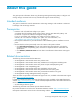
About this guide This guide provides information about using the Storage Management Utility (SMU) to configure and manage storage associated with an array controller that supports iSCSI networking. Intended audience This guide is intended for network administrators and storage managers with moderate or advanced knowledge of IP and storage networks. Prerequisites • Determine who will install and configure your system.
Additional related technical information includes: • • • • • • Internet Small Computer Systems Interface (iSCSI) rfc 3720: http://www.ietf.org/rfc/rfc3720.txt iSCSI Naming and Discovery: https://datatracker.ietf.org/public/pidtracker.cgi Internet Storage Name Service (iSNS): http://www.ietf.org/internet-drafts/draft-ietf-ips-isns-22.txt iSCSI and SLP: http://www.ietf.org/internet-drafts/draft-ietf-ips-iscsi-slp-09.txt Zeroconf: http://ietf.org/internet-drafts/draft-ietf-zeroconf-ipv4-linklocal-10.txt 802.
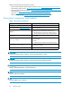
HP installation and configuration assistance Storage management and networking knowledge is required to successfully install this product. If you are not familiar with installing and configuring storage array systems, HP can install your system for you. For more information, access our website: http://www.hp.com/go/services. Under the Services Portfolio banner, select Infrastructure Services > Network Storage Services.
About this guide
1 Overview In this section: • • • • • Features and requirements Initial configuration methods Accessing the SMU Changing the management port IP address through the MSA1510i controller display panel Best practices Features and requirements The Storage Management Utility (SMU): • • • • • • • • • • • Configures and manages system storage. Resides on the array controller as part of the array controller firmware. Is accessed from a remote server or workstation using a browser.
Page description As shown in Figure 1, the interface includes five tabs, each of which is documented in detail in a separate section in this guide. Figure 1 SMU display — showing the five tabs • View—For viewing detailed configuration and status information. (For more information, see “View” on page 19”.) • Configure—For initially configuring a system, entering new information, or changing existing settings. (For more information, see “Configure” on page 25.
Accessing the SMU 1. Install, connect, and apply power to the storage and other network devices, as detailed in your system user documentation. 2. Obtain and record the IP address assigned to the primary management port (MA0). (Worksheets may be provided with you system installation instructions.
5. Wait a few moments for the utility to load. NOTE: When accessing the SMU for the first time, a window is displayed requiring input of a user-defined username and password. 6. One of the following happens: • If key components of the system are unconfigured, a prompt to go to the Wizard tab is displayed. (For more information, see “Wizards” on page 69.) • If the system is partially configured, the Configure tab is displayed. (For more information, see “Configure” on page 25.
2. Disable DHCP. a. With Network Settings displayed and blinking, press > to select it. b. Press ^ or v until DHCP Enabled is displayed and blinking, and then press > to select it. c. Press ^ or v to change the setting to No. d. Press < to accept the new setting and return to the initial management menu display. 3. Change the IP address. a. With Network Settings displayed and blinking, press > to select it. b. Press ^ or v until IP Address is displayed and blinking, and then press > to select it. c.
(MPIO multipathing software, etc.) in the configuration. Configure targets using portals on each controller. • Create fault-tolerant logical storage units—Create LUNs using fault-tolerant RAID levels and striping methods. • When assigning system names and aliases, use only the following characters: • Uppercase alpha characters (A-Z) • Lowercase alpha characters (a-z) • Numeric characters (0-9) • Special characters (! # = ( ) ‘ ; , .
2 View The Storage Management Utility (SMU) View tab is used to view system information. Included in this section: • Page description • Available tasks Page description As shown in Figure 2, the page is divided into 2 main sections: • System component list—Left side of page • Task list (and display area)—Right side of page Figure 2 View tab—showing the component and task lists Tabs Also shown in Figure 2 are the five tabs of the SMU: • View—For viewing detailed configuration and status information.
• Update—For updating MSA controller and module firmware. (For more information see “Update” on page 79.) Views As shown in Figure 3, expand the View drop-down box to select a viewing option. Your selection determines which system components are included in the component list: • All Devices—Displays all system components (Figure 2). • Devices with Alerts—Displays components for which any type of alert has been generated.
Figure 4 View tab—task listing The following tasks are available in the View tab: • • • • Viewing status alerts (View All Status Alerts) Viewing the event log (View Event Log) Refreshing the display (Refresh System) Identifying devices (Identify Device) Viewing status alerts (View All Status Alerts) Figure 5 illustrates some informational status alerts, generated when creating a logical drive.
Figure 5 View tab—View All Status Alerts page Viewing the event log (View Event Log) Figure 6 shows an example of a system event log. Figure 6 View tab—View Event Log page Refreshing the display (Refresh System) To refresh the SMU display, select Refresh System. The utility scans the configuration, and after a few moments, updates the display.
Identifying devices (Identify Device) To locate a system component by lighting up its LEDs, select the item from the component list, and then select Identify Device. For example, if this task is selected for a logical drive, the LEDs on the physical hard drives included in that logical drive are illuminated.
View
3 Configure The Storage Management Utility (SMU) Configure tab allows for complete system configuration and management. You can configure a new system, configure newly added components to an already-configured system, and make changes to an already-configured system.
• Configure—For initially configuring a system, entering new information, or changing existing settings. (For more information, see “Configure” on page 25.) • Wizards—For initially configuring a simple system. (For more information, see “Wizards” on page 69”.) • Diagnose—For generating an XML-formatted diagnostic report. (For more information, see “Diagnose” on page 77”.) • Update—For updating MSA controller and module firmware. (For more information see “Update” on page 79.
Available tasks Figure 9 Configure tab—task listing To perform a task in the SMU: 1. Select a system component from the list on the left side of the page. 2. Select a task from the list on the right side of the page. 3. Enter the requested information. NOTE: After selecting a component from the system list, a unique task list for that component is displayed. Table 2 lists the possible tasks for each system component.
Table 2 Available tasks, listed by system component System component Top-level storage system Management port TELNET Service SSH service HTTP Service HTTPS Service SNMP Service Data port Available tasks Where documented Create Array Creating arrays, page 39 Create iSCSI Target Creating storage targets, page 43 Add iSCSI Initiator Adding authorized initiators, page 49 Array Accelerator Settings Changing array or logical drive characteri stics, page 58 Storage System Settings Changing global se
System component Array Logical Drive Target Portal group Mapped Logical Drive Initiator Available tasks Where documented Create Logical Drive Creating logical drives, page 41 Spare Management Assigning spare drives to an array, page 40 Delete Deleting a component (Delete), page 63 Expand Array Changing array or logical drive characteri stics, page 58 Migrate RAID/Stripe size Changing array or logical drive characteri stics, page 58 Set Preferred Path Setting the preferred path (Preferred P
Sample configuration used in this document Illustrations in this document demonstrate the process of configuring a dual-controller MSA1510i storage system, with multiple targets being accessed by multiple initiators. Although each real-world environment and the associated configuration steps will differ from this example, fundamental principles of the configuration steps are the same for all installations.
Sample configuration—Physical-to-logical storage diagram 11 12 8 13 9 5 10 6 2 3 7 4 1 15293 Item Description 1 MSA1510i controller shelf and MSA20 storage enclosure Sample includes two array controllers and two 2-Port Ethernet iSCSI modules, with twelve SATA hard drives in the storage enclosure. 2 Array A Uses hard drives from bays 1, 2, 3, and 4. 3 Array B Uses hard drives from bays 5, 6, and 7, with number 11 assigned as a spare.
Sample configuration—Path/accessibility diagram 4 1 2 5 3 8 1 6 9 7 15294a Port IP address Portals Portal group Target 1 MA0 10.10.10.254 Not applicable Not applicable Not applicable 2 SA0 10.10.10.10 Portal 1: 3260 Portal 2: 3261 Group: 1 Group: 3 Target: 1 Target: 2 3 SA0 10.10.10.11 Portal 3: 3260 Portal 4: 3261 Group: 1 Group: 3 Target: 1 Target: 2 4 SA1 10.10.10.50 Portal 5: 3260 Portal 6: 3261 Group: 5 Group: 5 Target: 3 Target: 3 5 SA1 10.10.10.
Fundamental tasks, in initial configuration sequence Configuring a new system includes the following tasks, performed in the following sequence: • • • • Configuring management and data ports Configuring hard drives Creating storage targets Adding authorized initiators Configuring management and data ports As described in the installation documents, the array connects to the network switch from its Ethernet iSCSI module.
3. Select the Management Port on the controller and view the available tasks. 4. Select Management Port Settings.
5. Enter the settings for the management port. NOTE: • Port State must be Enabled (default) to use the SMU. If the management port state was disabled, you must use the Command Line Interface (CLI) to re-enable it. (For more information, see the Command Line Interface user guide.) • Assign a Host Name to the storage system (default: chassis serial number). HP recommends changing this to a more helpful user-defined value. • Port Name MA0 is the default management port.
1. Select Data Port > Add IP Address. 2. Enter settings for the data port. NOTE: • To control the path of storage traffic to and from the array controller and to add one level of system security, HP recommends assigning an IP Address to the data port that is in a different LAN segment than the management port. This IP address can not be changed. To change an IP address assigned to a port, you must add a new IP address and then delete the unneeded entry.
4. Select IP Address > Create Portal. 5. Enter settings for the portal. NOTE: For additional security, do not use commonly-known TCP ports. 6. When the display refreshes, verify that the newly configured portal is shown in the component list. 7. As needed for your environment, repeat Step 4 through Step 6 to assign additional TCP ports to this IP address. 8. Repeat Step 1 through Step 7 to add additional IP addresses to this data port or to configure the remaining data ports, such as SA1, SB0, and SB1.
Figure 10 Sample configuration—after configuring management and data ports NOTE: Due to the limited screen size, information for the management and data ports associated with the controller in slot 2 are not shown in Figure 10. Configuring hard drives Configuring hard drives includes two steps: • Creating arrays • Creating logical drives NOTE: For more information on configuring the storage, see “Storage overview” on page 85.
Creating arrays 1. Expand the View as drop-down box and select the Storage with iSCSI or Storage only view. 2. Select Storage System > Create Array.
3. Select the hard drives to include in the array. NOTE: • The SMU does not allow hard drives from SATA and SCSI storage enclosures to be included in the same array. • Hard drives included in an array should be the same size and speed. When drive sizes and speeds are mixed within an array, the usable capacity and the processing ability of the array is reduced to that of the smallest and slowest hard drive.
2. Select the hard drive(s) to assign as a spare. NOTE: • A spare must be the same type (SATA or SCSI) as other drives in the array. • A spare must be the same size (or larger) and speed (or faster) as other drives in the array. • A hard drive may be assigned as a spare to more than one array. • If a spare is assigned to an array, the words with Spare are included in the Array description. 3. Repeat Step 1 through Step 2 to assign spares to other configured arrays. Creating logical drives 1.
2. As needed, expand the drop-down boxes in the task area to change the settings from the suggested defaults. NOTE: • The SMU suggests defaults for the logical drive, creating one large logical drive from all unused space on the array, with the highest fault tolerance and performance possible for the hard drives included in that array. • Only Fault Tolerance levels possible for the array are displayed. For example, RAID 5 is not listed if the array has only two physical hard drives.
Figure 11 Sample configuration—after configuring hard drives Creating storage targets Configuring each storage target includes several steps: • • • • • Creating the target Creating target portal groups Assigning portals to the portal group Mapping logical drives to the target Configuring the redundant controller for a target (dual-controller configurations only) NOTE: This section illustrates the process of configuring an individual storage target.
2. Select Storage System and view the available tasks. 3. Select Create iSCSI Target. 4. Enter the requested information for the target. NOTE: • The utility suggests default values for the Target Name and Alias that adhere to iSCSI standards. To accept the defaults, click OK. • This step creates the target entity; additional steps build information behind the target. 5. When the display refreshes, verify that the new target is shown in the component list.
Creating target portal groups 1. Select Target > Create Portal Group. 2. Enter the requested information for the portal group. NOTE: • The utility suggests a default Portal Group Alias. Accept the default or enter a user-defined value. • This step creates the portal group entity; additional steps build information behind the portal group. 3. When the display refreshes, expand (+) all components listed for the target and verify that the newly added portal group is shown in the component list.
Assigning portals to the portal group 1. Select Portal Group > Assign Portals. 2. Expand the Port Name drop-down box and select the data port for this portal group to use. 3. Select the portals for this portal group to use. NOTE: • When assigning portals to a target's portal group, you are designating the path for traffic to and from that target. • Only IP addresses and portals associated with the selected data port are displayed.
Mapping logical drives to the target 1. Select Target > Map Logical Drive to Target. 2. Enter the requested information for the mapped logical drive. NOTE: • The utility suggests a default value for the Mapped LUN Alias. Accept the default or enter a user-defined, content-descriptive value. • The utility suggests a default number to assign to the mapping, beginning with number 1. Accept the default or expand the drop-down box to select a different number. HP recommends accepting the default.
2. Select the newly created Portal Group > Assign Portals. Expand the Port Name drop-down box and select a port on the redundant Ethernet iSCSI module for this target portal group to use. After the portals associated with the selected logical port are displayed, select the TCP portals to use. Configuration status - after creating storage targets Figure 12 illustrates the current configuration.
Figure 12 Sample system configuration—after configuring targets NOTE: Figure 12 illustrates the following for Target 1: • One logical drive (Logical Drive 1) is mapped to this target. • Primary and redundant paths are defined for this target: • Portal Group “pg1” uses two portals on data port SA0 of the primary Ethernet iSCSI module. • Portal Group “pg2” uses two portals on data port SB0 of the redundant Ethernet iSCSI module. Adding authorized initiators 1. Select Storage System > Add iSCSI Initiator.
2. Enter the requested information for the iSCSI initiator. NOTE: • The iSCSI Initiator Name is assigned when defining the initiator on the server, and is usually in the format of “iqn.xxx”. Obtain initiator names from your network administrator or as displayed in the iSCSI initiator software on the server. • Be sure to enter the iSCSI Initiator Name exactly as assigned in the iSCSI initiator software on the server. Include all special characters, including periods, and spaces.
Figure 13 Sample configuration—after adding initiators IMPORTANT: Perform the following tasks to complete the configuration: • Enter security settings (optional, but recommended). (For more information, see “Security tasks” on page 51.) • Enter configuration settings in the iSCSI initiator configuration software utility (on the server), including: • Adding target portals for the initiator to access. • Configuring the target portals.
2. Select Target > Enable/Disable Access Control. 3. Expand the ACL State drop-down box, and enable access control. 4. The following warning message is displayed: 5. Confirm that there is no active I/O on the target, and then click OK. IMPORTANT: • To prevent loss of access to the storage, ACLs should not be modified if there is an active session between the initiator and the target.
6. Select Mapped Logical Drive > Update Access Control. NOTE: Update Access Control is listed as a common task only if Access Control is enabled (Step 2). 7. Select the initiators that can access this mapped logical drive. 8. Repeat Step 6 through Step 7 for each mapped logical drive of the target. 9. If necessary, repeat Step 1 through Step 8 to set up an ACL for a different target.
1. In the SMU, select Storage System > Canonical Target CHAP Settings. 2. Expand the CHAP State drop-down box and change the setting to Enabled. NOTE: If Canonical Target CHAP settings have already been entered, the display is contracted and protected by a gateway check box. To change existing CHAP settings, clear the Use Existing CHAP Settings check box. The page expands, allowing access to the settings. 3. Enter the CHAP Secret in the provided spaces. 4.
1. In the SMU, select Target > CHAP Settings. 2. Expand the CHAP State drop-down box and change the setting to Enabled. NOTE: If CHAP settings have already been entered for this target, the display is contracted and protected by a gateway check box. To change existing CHAP settings, clear the Use Existing CHAP Settings check box. The page expands, allowing access to the settings. 3. Enter the CHAP Secret. 4. On the server, open the iSCSI initiator software utility.
2. To enter an initiator-specific CHAP secret in both the SMU and in the iSCSI initiator software utility: a. On the server, open the iSCSI initiator software utility. Navigate through the iSCSI initiator software utility and either assign a CHAP secret to the initiator or record the existing CHAP secret. b. In the SMU, select Initiator > CHAP Settings. Then, enter the same CHAP secret assigned to the initiator the iSCSI initiator software utility. 3.
1. Select Management Port > Set SSL Certificate. 2. Expand the SSL Certificate Type drop-down box and select Upload PEM Certificate. 3. Enter the requested information.
Adding a route (Add Route) To add an entry to the route table for this controller: 1. Select a data port from the system component list, and then select the Add Route task. 2. Enter the IP information for the route.
IMPORTANT: • Completion time of an array expansion, logical drive extension, or logical drive migration varies, depending on the drive speed and type, system array controller settings, and existing storage configuration. (Process times of 36 to 72 hours are common.) • During an expansion, extension, or migration, access to the data is permitted, but at a reduced performance rate. • During an expansion, extension, or migration, the risk of data loss if a drive fails is increased.
• Create new logical drives on the array. (For more information, see “Creating logical drives” on page 41.) • Migrate the RAID level or stripe size of existing logical drives on the array (For more information, see“Migrating to a different RAID level or stripe size (Migrate RAID/Stripe Size)” on page 60.) • Extend the storage capacity of an existing logical drive on the array. ((For more information, see “Extending a logical drive (Extend Logical Drive)” on page 60.) To expand the capacity of an array: 1.
3. Select Logical Drive > Migrate Logical Drive. 4. Enter the new settings for the logical drive. Changing global settings (Storage System Settings) The default global settings are adequate for most environments. If needed, use this option to: • Change the ratio of memory allocated to read and write operations. • Change the priority of array expansions relative to normal operations. • Change the priority of array rebuilds relative to normal operations. To change the default global settings: 1.
2. Enter the new values. NOTE: • The Cache Ratio determines the amount of memory allocated to read and write operations. For improved performance, you may want to change this ratio to allocate more memory to write operations, as high as 10% read/90% write.
1. Select Storage System > Clear Configuration. 2. Select the configuration components to clear. NOTE: • Select all—Clears all iSCSI, storage, and management configuration settings. • iSCSI Configuration—Clears iSCSI configuration settings only. • Management Configuration—Clears management configuration settings only. • Storage Configuration—Clears storage configuration settings only.
NOTE: Some of the components that can not be deleted while in use include: • Removing a portal from a portal group • Deleting a portal group • Deleting a target Disabling automatic path switching (Redundancy Settings) NOTE: This task is available for dual-controller configurations only. 1. Select Storage System > Redundancy Settings. 2.
Enabling iSNS discovery Enabling iSNS discovery of storage targets includes: • Enabling iSNS discovery (iSNS Discovery Settings) • Enabling iSNS discovery of specific targets (Discovery Settings) Enabling iSNS discovery (iSNS Discovery Settings) 1. Select Storage System > iSNS Discovery Settings. 2. Expand the drop-down boxes to enable iSNS discovery and enter other iSNS settings.
Enabling iSNS discovery of specific targets (Discovery Settings) 1. Select Target > Discovery Settings. 2. Expand the drop-down boxes to Enable SLP and/or iSNS Discovery. Identifying devices (Identify Device) To locate a system component by lighting up its LEDs, select the item from the component list, and then select Identify Device. For example, if this task is selected for a logical drive, the LEDs on the physical hard drives included in that logical drive are illuminated.
Setting the preferred path for a LUN (Preferred Path) NOTE: This task is available for dual-controller configurations only. To manually (explicitly) set controller ownership of a LUN: 1. Select an already-configured logical drive from the system component list, and then select the Preferred Path task. 2. Expand the Preferred Path drop-down box and select a controller.
NOTE: Make note of the icon displayed next to each system component. Icons provide at-a-glance status of each component. (For more information about status icons, see “Icon descriptions” on page 91.) Viewing status alerts (View All Status Alerts) Available in both the Configure and View tabs, View All Status Alerts shows the following alerts: • Informational • Degraded • Critical The following image illustrates the informational status alerts generated during the configuration of a logical drive.
4 Wizards The Initial System Configuration Wizard is the easiest and simplest method to initially configure your system. You are prompted in a logical sequence for storage, iSCSI, logon, and management settings. The wizard then uses those settings to configure the storage as an iSCSI target and make it available to the iSCSI initiator. NOTE: This configuration method is best for single-server environments needing bulk storage: • One IP address is assigned to each data port. • One target is created.
3. In the initial Welcome page, expand the drop-down box on the left side of the page to display the steps included in the wizard. 4. When prompted, click Next.
5. In the Storage Configuration page, enter configuration settings for the logical drive. NOTE: • The wizard suggests a Fault Tolerance (RAID) level, unique to each installation, based on the detected number of storage enclosures, enclosure type (SATA or SCSI), number of available hard drives, drive generation, speed, and size. To select a different RAID level, expand the Fault Tolerance drop-down box.
6. In the iSCSI Configuration page, enter values for one of the data ports. NOTE: • By default, the wizard recommends configuring Data Port SA0. HP recommends accepting the default. • Assign an IP Address to the data port. • VLANs are set up on the switch and are used as one method of controlling access to the storage. If using VLANs, enter the VLAN ID to use (0 = not used). • The wizard suggests a default iSCSI Target Name and iSCSI Target Alias. Accept the default or enter user-defined values.
7. In the Logon Settings page, specify if you want to change access information. NOTE: To change the logon username and password, clear Use Existing Administrator ID and Password. The Logon Settings page expands, with options to change the Admin ID and Password.
8. In the Management Settings window, enter settings for the management port. NOTE: • Port State must be Enabled (default) to use the SMU. To re-enable SMU management, you must use a Command Line Interface (CLI) command. For more information, see the Command Line Interface user guide. • Assign a Host Name to the storage system. (Default: chassis serial number) • By default, the wizard suggests configuring Logical Port Name MA0 as the primary management port. HP recommends accepting the default.
9. After completing all steps of the wizard, a final confirmation window is displayed. • Click • Click • Click 10. Wait for Finish to apply the configuration settings. Back to change settings. Cancel to exit the wizard. the utility to apply your settings. 11. After all settings have been applied, you may need to change the IP address of your management client device to be in the same subnet as the address assigned to the management port. 12.
Wizards
5 Diagnose The Storage Management Utility (SMU) Diagnose tab is used to generate diagnostic information about the array controller. 1. Click Generate Report.
2. After a few moments, the report is displayed in a separate window. 3. As needed, use the options available in the report window menu bar to edit or save the diagnostic information to a file.
6 Update Updating system firmware (Flash Firmware) Available tasks As shown in Figure 14, the Update tab includes two options: • Updating MSA firmware • Updating hard drive firmware Figure 14 Update tab—task listing Prerequisites Before updating system firmware, make note of the following: • When determining which MSA controller firmware version to use, review the requirements and information in the Compatibility Matrix(es), release notes, and other MSA announcements.
• If it has been more than six months since you restarted your MSA storage system, HP recommends that you power-cycle the MSA (power off, and then power on) before updating the firmware to ensure that you are working with a fresh system. • For newly installed MSA, do not perform a firmware update until controller batteries are fully charged. • For existing MSA, do not perform a firmware update until you have confirmed that the “host mode” or “profile” for each connection is correctly set.
2. Obtain the latest firmware files and save to a temporary location on the host: a. Go to the MSA1510i Support page: http://www.hp.com/support b. Select your language. c. Select your operating system. The display is updated to include a list of available downloads for the specified operating system. d.
7. From within the SMU, select Update > Controller > Flash Firmware. 8. Under the Flash Firmware banner, click Browse and navigate to the location of the previously-obtained firmware file, and then click OK. 9. Wait for a completion message to display.
11. View the messages displayed on the array controller LCD panel during startup to confirm that the firmware was installed successfully and that the array controller restarts successfully. NOTE: In dual-controller configurations, firmware on the two controllers is compared each time the MSA chassis is restarted. If the versions are mismatched, the system prompts to clone the firmware on the controller with the latest version over to the controller with the earlier version firmware.
4. Open a browser and access the SMU. 5. Select Update > Storage System > Flash Firmware. 6. Under the Upload Inventory Firmware XML File banner, click Browse, navigate to the location of the previously-obtained XML firmware file, select an updating option, and then click OK. 7. Wait for the MSA1510i to process the XML file and update the display with a list of all Smart Components that need updating. 8. In the updated display, select a Smart Component from the list. 9.
A Storage overview • • • • Arrays and logical drives Fault-tolerance levels Comparison of RAID Methods Choosing a RAID level Arrays and logical drives The capacity and performance of a single physical hard drive is adequate for home users. However, business users demand higher storage capacities, higher data transfer rates, and greater protection against data loss when a hard drive fails.
S1 S2 S3 S4 B1 B2 B3 B4 B5 B6 B7 B8 B9 B10 B11 B12 D1 D2 D3 15312 Figure 17 Data striping (S1-S4) and data blocks (B1-B12) on multiple physical drives (D1, D2, D3) For data in the logical drive to be readable, the data block sequence must be the same in every stripe. This sequencing process is performed by the array controller, which sends the data blocks to the drive write heads in the correct order.
that was originally on the failed drive to the online spare. The system is quickly restored to full RAID-level data protection. (In the unlikely event that another drive in the array fails while data is being rewritten to the spare, the logical drive will still fail.) A spare is assigned to an array and is automatically assigned to all logical drives in the same array. You do not need to assign a separate spare to each array; you can configure one hard drive to be the spare for several arrays.
S1 B1 B2 B3 B4 S2 B5 B6 B7 B8 D1 D2 D3 D4 D5 D6 D7 D8 S1 B1 B2 B3 B4 S2 B5 B6 B7 B8 15315 Figure 20 RAID 1+0 array, with eight physical hard drives (D1 through D8) In each mirrored pair, the physical drive that is not busy answering other requests answers any read request sent to the array. (This behavior is called load balancing.) If a physical drive fails, the remaining drive in the mirrored pair can still provide all the necessary data.
Table 5 RAID 5 features Advantages Disadvantages High read performance. Relatively low write performance. No loss of data if one physical drive fails. Loss of data if a second drive fails before data from the first failed drive is rebuilt. More usable drive capacity than RAID 1+0, because parity information requires the storage space equivalent to one physical drive.
Table 7 Summary of RAID methods RAID 0 RAID 1+0 RAID 5 RAID 6 Alternative name Striping Mirroring Distributed Data Guarding (DDG) Advanced Data Guarding (ADG) Usable drive space* 100% 50% 67% to 93% 50% to 96% Usable drive space formula n n/2 (n-1)/n (n-2)/n Minimum number of physical drives 1 2 3 4 Tolerates physical drive failure? No Yes Yes Yes Tolerates simultaneous failure of more than one physical drive? No Only if no two failed drives are in a mirrored pair No Yes Re
B Icon descriptions Table 9 describes SMU icons.
Icon Meaning Initiator Logical drive Logical drive—Being expanded (animated icon) Logical drive—Being rebuilt (animated icon) SATA array SATA hard drive SATA hard drive—Spare SATA hard drive—Active spare (animated icon) SATA hard drive—Being rebuilt (animated icon) SATA hard drive—Active spare—Being rebuilt (animated icon) SCSI array SCSI hard drive SCSI hard drive—Spare drive SCSI hard drive—Active spare (animated icon) SCSI hard drive—Being rebuilt (animated icon) SCSI hard drive—Active spare—Being re
Icon Meaning Status—Critical Status—Degraded Status—Okay Status - Pause/standby Help More information is available for this component. View the status alerts.
Icon descriptions
Index A Access Control Lists (ACLs), 51 access permissions, default settings, 15 accessing SMU first time, 16 accessing the SMU, 15 Add IP Address task, described, 36 Add iSCSI Initiator task, described, 49 advanced data guarding (See RAID 6.
data protection methods (See also RAID levels.), 86 data stripes, defined, 85 default access permissions, 15 Delete task, described, 63 deleting components, 63 DHCP Setting, 35, 36 Diagnose tab described, 77 diagrams hardware/device, 30 path/accessibility, 32 storage, 31 Disable Standby Controller task, described, 64 disabling the array accelerator, 59 disabling the standby controller, 64 Discovery Settings task, described, 66 distributed data guarding (See RAID 5.
M management port changing through MSA1510i display, 16 configuration , dual-controller, 35 configuring, 33, 33 initial IP address, 15 IP address changing, 16 settings, 35 SSL certificate, 57 Management Port Settings task, described, 34 management traffic control, 74 management, configuration tasks additional, 57 Map Logical Drive to Target task, described, 47 mapped logical drive Alias name for, 47 for a target, 47 granting access to, 53 Migrate RAID/Stripe Size task, described, 60 mirroring of drives (Se
SMU accessing, 15 best practices, 17 feature list, 13 icons, 91 overview, 13 tab descriptions, 25 SMU hard drive RAID level, 18 spare drives assigning to an array, 40 defined, 87 recommendations, 41 Spare Management task, described, 40 SSL certificate, setting up, 56 standby controller, disabling, 64 storage recommendations, 40 viewing options, 26 Storage System Settings task, described, 61 Storage view, 26 Storage with iSCSI view, 26 Stripe Size, 42 striping, described, 85 Subscriber's Choice, HP, 11 suppo
View tab described, 19 page description, 19 viewing component information, 67 viewing options, 20 viewing system event log, 22 viewing system status alerts, 21 VLAN best practice, 17 ID, 35, 36 W websites HP , 11 HP documentation, 9 HP Storage, 9 HP Subscriber's Choice for Business, 11 product manuals, 9 Wizard tab additional concluding tasks, 75 availability of, 69 described, 14, 69 HP Storage Management Utility user guide 99