
HP StoreEver MSL6480 Tape Library User and Service Guide Addendum (QU625-96016, October 2013)
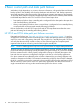
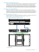
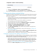

In the typical bridged library controller connection each tape drive has one physical link to the
SAN switch and connects to the SAN switch as one Fibre Channel device.
The tape drive hosting the library controller path connects as one Fibre Channel device containing
two logical units. The tape drive is logical unit number zero and the tape library is logical unit
number one. Both devices are considered to be in the same Fibre Channel device which is called
a “Node”. The tape library Fibre Channel node contains a tape drive logical unit and a media
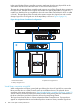
changer logical unit. The logical view of the tape library is shown in Figure 8 (page 16).
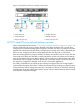
Figure 8 Logical view of traditional configuration
1
2
3
2. Tape Drive at logical unit 01. Fibre Channel node
3. Library at logical unit 1
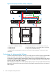
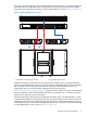
Virtual library connection using NPIV
When configured to use library control path port failover, the drive will use NPIV to connect the
library and the drive to a Fibre Channel switch as two different devices. The physical device
connection is the same as that shown in “Typical bridged library controller connection” (page 15)
with the internal connection between the library and the drives passing the host commands from
the drive to the library and the link from the drive to the switch being shared.
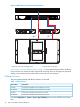
The logical view from the host is of three independent Fibre Channel devices. Two tape drives
appear as independent devices and neither tape drive contains a library controller logical unit.
16 Basic control path and data path failover