HP StorageWorks Multi-protocol router installation guide Part number: A7437-96003 Third edition: September 2005
Legal and notice information © Copyright 2005 Hewlett-Packard Development Company, L.P. © Copyright 2005 Brocade Communications Systems, Incorporated. Hewlett-Packard Company makes no warranty of any kind with regard to this material, including, but not limited to, the implied warranties of merchantability and fitness for a particular purpose.
Contents About this guide . . . . . . . . . . . . . . . Contents .................................. 9 Intended audience . . . . . . . . . . . . . . . . . . . . . . . . . . . . . . . . . . . . . Related documentation . . . . . . . . . . . . . . . . . . . . . . . . . . . . . . . . . . Document conventions and symbols . . . . . . . . . . . . . . . . . . . . . . . . . Rack stability . . . . . . . . . . . . . . . . . . . . . . . . . . . . . . . . . . . . . . . . . HP technical support . . . . . . . . . . . . . .
Power On Self-Test . . . . . . . . . . . . . . . . . . . . . . . . . . . . . . . . . . . . . . . . . . . . . . . . . . . . . Bypassing POST . . . . . . . . . . . . . . . . . . . . . . . . . . . . . . . . . . . . . . . . . . . . . . . . . . . . Checking POST results . . . . . . . . . . . . . . . . . . . . . . . . . . . . . . . . . . . . . . . . . . . . . . . . Recommendations for cable management . . . . . . . . . . . . . . . . . . . . . . . . . . . . . . . . . . . . . Installing SFP transceivers . . . . . .
Replacing FRUs . . . . . . . . . . . . . . . . . . . . . . . . . . . . . . . . . . . . . . . . . . . . . . . 67 Replacing a power supply . . . . . . . . . . . . . . . . . . . . . . . . . . . . . . . . . . . . . . . . . . . . . . . . . . Time required . . . . . . . . . . . . . . . . . . . . . . . . . . . . . . . . . . . . . . . . . . . . . . . . . . . . . . . . Items required . . . . . . . . . . . . . . . . . . . . . . . . . . . . . . . . . . . . . . . . . . . . . . . . . . . . . . . . Procedure . . . . .
Waste Electrical and Electronic Equipment directive . . . . . . . . . . . . . . . . . . . . . . Czechoslovakian notice . . . . . . . . . . . . . . . . . . . . . . . . . . . . . . . . . . . . . . . Danish notice . . . . . . . . . . . . . . . . . . . . . . . . . . . . . . . . . . . . . . . . . . . . . . Dutch notice . . . . . . . . . . . . . . . . . . . . . . . . . . . . . . . . . . . . . . . . . . . . . . . English notice . . . . . . . . . . . . . . . . . . . . . . . . . . . . . . . . . . . . . . . . . . . .
2 3 4 5 6 7 8 9 10 11 12 13 14 15 16 17 18 19 20 21 22 23 Port side component descriptions . . . . . . . . . . . . . . . . . . . . . . . . . . . . . . . . . . . . . . . . . Nonport side component descriptions . . . . . . . . . . . . . . . . . . . . . . . . . . . . . . . . . . . . . MP Router orderable hardware . . . . . . . . . . . . . . . . . . . . . . . . . . . . . . . . . . . . . . . . . . Shipping carton contents . . . . . . . . . . . . . . . . . . . . . . . . . . . . . . . . . . . . . . . . . . . . .
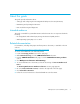
About this guide This guide provides information about: • Setting up and configuring the HP StorageWorks Multi-protocol Router (MP Router) • Maintaining and operating the MP Router • Basic troubleshooting and diagnostics Intended audience This guide is intended for system administrators and technicians who are experienced with the following: • HP StorageWorks Fibre Channel (FC) Storage Area Network (SAN) switches • XPath Operating System (OS) 7.4.
Document conventions and symbols Table 1 Document conventions Convention Element Medium blue text: Figure 1 Cross-reference links and e-mail addresses Medium blue, underlined text (http://www.hp.
Rack stability WARNING! To reduce the risk of personal injury or damage to equipment: • Extend leveling jacks to the floor. • Ensure that the full weight of the rack rests on the leveling jacks. • Install stabilizing feet on the rack. • In multiple-rack installations, secure racks together. • Extend only one rack component at a time. Racks may become unstable if more than one component is extended.
Helpful web sites For other product information, see the following HP web sites: • http://www.hp.com • http://www.hp.com/go/storage • http://www.hp.com/support/ • http://www.docs.hp.
1 Overview The MP Router is a high-performance, 8-port or 16-port, 2 gigabit (Gb) router that passes data between storage devices, hosts, and servers in a Storage Area Network (SAN). The MP Router integrates XPath OS 7.4.x, and is compatible with the HP StorageWorks switch product family. MP Router models include: • HP StorageWorks Multi-protocol Router Base—An 8-port multi-protocol router providing FC Subnet Routing, FCIP Tunneling and iSCSI Gateway service.
The system chassis is a 2 Unit (U) high enclosure with space to contain two hot-pluggable n+1 power supply units, the motherboard, the control system daughter card, the power regulator board, and dual hot-pluggable fan assemblies. Port side The MP Router’s port side, shown in Figure 1 and Table 2, includes two 320-watt removable, redundant power supplies with hot-swappable capability, Fibre Channel ports, management ports, and a serial port.
Table 2 Port side component descriptions (continued) Item Summary 6 Management port LEDs Indicate Management port activity including speed and link status. 7 Power supply LEDs Indicate normal power output or failure. 8 Power supply Each power supply provides three DC outputs (5V standby, 12V, and 48V), providing a total output power of 320 maximum usable watts. 9 Power supply status LEDs Indicate power supply input/output functioning properly or alert user to replace a faulty power supply.
Multi-protocol ports The MP Router integrates sixteen multi-protocol ports (numbered 0—15, left to right). If you purchased the MP Router Base model, ports 0—7 are enabled. If you purchased the MP Router Full model, all ports are enabled. IMPORTANT: If you purchased the MP Router with only eight active ports, you can enable the remaining eight ports by purchasing the HP StorageWorks MP Router Upgrade License. See ”Upgrading an 8-port base model to a 16-port full model” on page 19 for more information.
Nonport side The MP Router’s nonport side, shown in Figure 2 and Table 3, includes dual hot-pluggable cooling fan assemblies with LEDs (containing three fans each) and system status LEDs. The system status LEDs are described in ”Interpreting LED activity” on page 51. 3 2 1 PORTS SYSTEM FAN OK FAN OK FAN FAIL FAN FAIL 6 4 5 MRO25004a Figure 2 MP Router (Nonport side) Table 3 Nonport side component descriptions Item Summary 1 Fan assembly (2) The chassis contains two fan assembly slots.
Software features XPath OS 7.4.x runs on the MP Router. The firmware provides full Fibre Channel switch capability, FC-FC Routing Service, and Fibre Channel over IP tunneling. You can configure individual ports on the MP Router to support the switch functionality or services that you need. Fibre Channel switch support XPath OS 7.4.x includes the following Fibre Channel features: • Name Server support • Zone Server support • ISL exchange-based trunking See the HP StorageWorks XPath OS 7.4.
FCIP Tunneling service The FCIP Tunneling service enables passive Fibre Channel frames to “tunnel” through TCP/IP networks by encapsulating them in TCP packets and then reconstructing them at the other end of the link. NOTE: XPath OS supports FCIP only between two MP Routers. See the HP StorageWorks XPath OS 7.4.x administrator guide for additional FCIP Tunneling information. User interfaces XPath OS 7.4.
Example MPRouter:admin> licenseadd "bQebzbRdScRfc0iK" License key bQebzbRdScRfc0iK added c. After entering the license key, use the licenseshow command to see whether the license is valid. If a licensed product is not displayed, the license is invalid. NOTE: After a license is entered, the licensed product is available immediately; the system does not require a reboot. 11.Configure the inactive ports.
Optional hardware kits Table 4 lists MP Router optional hardware kits.
Overview
2 Installation, setup, and login This chapter provides the following information: • Unpacking and verifying carton contents, page 23 • Locating MP Router serial numbers, page 23 • Carton contents checklist, page 24 • Installation guidelines, page 25 • Installation time and items required, page 26 • Setting up the MP Router as a stand-alone unit, page 27 • Installing the MP Router in a rack using the SAN Switch Rack Mount Kit, page 28 • Connecting AC power, page 37 • Power On Self-Test, page 38 • Recommenda
Carton contents checklist Table 5 Shipping carton contents Item Description 1 One MP Router populated with two power supplies and two fan assemblies 2 An MP Router product accessories box containing: • One RS-232 serial cable; can be converted from a DB-9 to a RJ-45 connector, by removing the adapter on the end of the cable • Pouch containing rack mount hardware: • (14) #8-32 x 3/16-inch Phillips pan-head screw with thread lock for the SAN Switch 2/32 only • (14) 8-32 x 5/16-inch Phillips pan-head SE
Installation guidelines Install the MP Router using one of the following methods: • As a stand-alone unit on a flat surface • In a 19-inch Electronic Industries Association (EIA) rack, using the HP StorageWorks SAN Switch Rack Mount Kit (included with the MP Router) CAUTION: To ensure adequate cooling, install the chassis with the nonport side facing the air-intake aisle. This prevents the fans from pulling in heated exhaust air.
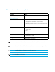
Installation time and items required Table 6 lists the main installation and setup tasks and the estimated time and items required for each task. The time estimates assume a prepared installation site and appropriate power and network connectivity.
Setting up the MP Router as a stand-alone unit Follow this procedure to set up the router as a stand-alone unit. The following items are required for this setup. • MP Router • AC power cords and cables supplied with the router • Rubber mounting feet supplied with the router 1. Place the MP Router on a flat, sturdy surface such as a table or lab bench. 2. Apply the rubber feet as follows: a. Clean the four depressions located at each corner of the bottom of the router to ensure they are free of dust. b.
Installing the MP Router in a rack using the SAN Switch Rack Mount Kit This section provides instructions for installing the MP Router in an HP System/e rack, or in an HP 10000 series rack using the HP StorageWorks SAN Switch Rack Mount Kit supplied with your router. This installation requires one technician.
Table 7 Item Rack Mount Kit rails and rail mounting hardware (continued) Description (8) #10 alignment washers (8) #10 adapter washers (2) 1/4-20 hex nuts with captive star lock washers (2) 1/4-inch flat washers CAUTION: For proper air flow, the SFP media side of the MP Router must face the rear of the rack. This mounting allows air to enter from the front of the rack and to exhaust at the rear of the rack, similar to other rack-mounted equipment. This prevents overheating, which can cause failures.
• For an HP 10000 series rack, assemble each of the two brackets with two #10-32 x 1/2-inch Phillips pan-head screws with captive star lock washers and two #10 adapter washers as shown in Figure 3.
• For an HP System/e rack, install each of the two rear mounting brackets with two #10-32 x 1/2-inch Phillips pan-head screws and two #10 alignment washers as shown in Figure 4. Figure 4 Installing the rear mounting brackets (HP System/e rack—left rear upright) NOTE: This kit contains both left rails and right rails. The rails are labelled Right and Left.
4. Assemble the outer rails by completing the following steps: a. Attach the left outer rail and the right outer rails to the rear mounting brackets using two 1/4-20 hex nuts with captive star lock washers. Attach the hex nuts loosely (as shown in Figure 5). Do not tighten; tighten the hex nuts later in step 7 on page 37.
b. Depending on the rack you are using, complete one of the following tasks: • For an HP 10000 series rack, install two #10-32 x 1/2-inch Phillips pan-head screws with captive star lock washers and two #10 adapter washers in the upper and lower hole locations of the right rail. Then install two #10-32 x 1/2-inch Phillips pan-head screws with captive star lock washers and two #10 adapter washers in the upper and lower hole locations of the left rail, as shown in Figure 6.
• For an HP System/e rack, install two #10-32 x 1/2-inch Phillips pan-head screws with captive star lock washers and two #10 alignment washers in the upper and lower hole locations of the right rail. Then install two #10-32 x 1/2-inch Phillips pan-head screws with captive star lock washers and two #10 alignment washers in the upper and lower hole locations of the left rail, as shown in Figure 7.
5. For both HP 10000 series and HP System/e racks, use the mounting holes shown in Figure 8 to attach the two inner rails (one on each side) to the MP Router. Use six screws (three on each side) of the 8-32 x 5/16-inch Phillips pan-head SEMS screws as shown in Figure 8. When viewing a rack from the front, the left rails are used in the left side of the rack and the right rails are used in the right side of the rack. The rails must match up—right inner with right outer and left inner with left outer.
6. Insert the router into the rack and install two #10-32 x 1/2-inch Phillips pan-head screws with captive star lock washers, one on each side, as shown in Figure 9 and Figure 10.
7. Tighten the nuts installed in step 4a on page 32. NOTE: To uninstall a router, remove the middle #10-32 x 1/2-inch Phillips pan head screw with captive star lock washer from either side of the rack uprights. Connecting AC power Follow these steps to power on the MP Router. CAUTION: Do not plug the power cords into the power source until the MP Router is completely installed in the rack. 1. Connect the two MP Router power cords to the power inlets on the switch.
Power On Self-Test Each time the router is powered on, rebooted, or reset, it automatically runs POST. During POST, the port status LEDs flash, verifying that the router is operating properly. POST completes in approximately 3 minutes, with a total boot time of approximately 6 minutes.
Example ******************************************************************************* * * * Copyright (c) 2004, * * MP Router* * Firmware Version 1.x.x.x.
Recommendations for cable management Follow these suggestions for better cable organization and management: • Plan cable management before installing the MP Router to ensure adequate rack space. • Leave at least one meter of slack for each port cable. This provides room to remove and replace the MP Router, allows for inadvertent rack movement, and helps prevent the cables from being bent to less than the minimum bend radius.
5. Connect the cables to the SFPs: CAUTION: A 50-micron cable should not be bent to a radius less than 2 inches under full tensile load and 1.2 inches with no tensile load. Tie wraps are not recommended for optical cables because they are easily overtightened. a. Orient a cable connector so that the key (the ridge on one side of the connector) aligns with the slot in the SFP. b. Insert the cable into the transceiver until the latching mechanism clicks (see Figure 15 on page 74).
7. When the terminal emulator application stops reporting information, press Enter. 8. Log in to the MP Router as admin. The default password is password. At the initial login, you are prompted to enter your own personal admin and user passwords. 9. Modify passwords, if desired. Passwords can be 8 to 40 characters and should include a combination of numbers and upper and lowercase letters. To skip this step, press Ctrl-C. Example XPath OS Switch login: admin Password: Please change your passwords now.
3 Setting initial parameters This chapter provides the following information: • First time configuration checklist, page 43 • Setting the IP address, page 43 • Establishing an Ethernet connection, page 45 • Setting the domain ID, page 45 • Setting the date and time, page 46 • Connecting the MP Router to the fabric, page 48 • Viewing, adding, and removing licenses, page 48 • Verifying operation, page 50 • Backing up the configuration, page 50 NOTE: This chapter provides the basic steps required for the init
See Table 8 for a list of syntaxes to use with the ipAddrSet command.
CAUTION: The console port can be used to monitor error messages through a serial connection. It is not recommended as a command interface during normal operation. If this port is not in use, remove the serial cable and protect the port from dust by replacing the shipping plug. Record the IP address on the label affixed to the MP Router. Establishing an Ethernet connection After using a serial connection to configure the IP address for the MP Router, connect to the Local Area Network (LAN) if desired.
4. Enter the appropriate parameters for the remaining prompts. 5. Enter the switchenable command to re-enable the MP Router. Setting the date and time The MP Router maintains the current date and time in nonvolatile memory. The date and time are used for logging events. Set the correct date and time (and time zone) for the MP Router to prevent management interfaces, such as Advanced Web Tools, from displaying incorrect event times.
Example APswitch:admin> timezoneset Please select a continent or ocean 1). Africa 2). America 5). Asia 6). Atlantic Ocean 9). Indian Ocean 10). Pacific Ocean 3). Antarctica 7). Australia 11). US 4). Arctic Ocean 8). Europe 12). Canada Enter the option #: 11 Please select a country or city 1). Alaska 2). Aleutian 5). East-Indiana 6). Eastern 9). Michigan 10). Mountain 13). Samoa Enter the option #: 12 3). Arizona 4). Central 7). Hawaii 8). Indiana-Starke 11). Pacific 12).
Connecting the MP Router to the fabric Before connecting the MP Router to the fabric, install the SFP transceivers (see ”Installing SFP transceivers” on page 40). Verify that all the switches in the fabric use the correct port identifier (PID) settings. For complete information on setting the PID settings, see the HP StorageWorks XPath OS 7.4.x administrator guide. Use these steps to connect the MP Router to the fabric. 1.
Example APswitch:admin> licenseshow License Key: bQebzeRdScRfc0iK Web License Key: SybbzQQ9edTzcd0X Zoning License Key: SybbzQQ9edTzcc0X Trunking License Key: cSzbbcdyQbdb0csv FCIP APswitch:admin> Adding a license Contact your HP-authorized reseller to purchase license keys for optional features. A license key is a string of approximately 16 uppercase and lowercase letters and digits. Your HP representative requires the MP Router’s World Wide Number (WWN) in order to assign a license key.
Removing a license Use these steps to remove a license from the MP Router. 1. Log in to the MP Router as admin. 2. Enter the licenseremove command, followed by the license key enclosed in double quotation marks. Example APswitch:admin> licenseremove "bQebzbRdScRfc0iK" removing license key "bQebzbRdScRfc0iK" 3. Remember to save the license key in case you want to reinstall the license in the future. Verifying operation Use these steps to verify that the MP Router is set up and connected. 1.
4 Monitoring the MP Router This chapter provides the following information: • Interpreting LED activity, page 51 • Management overview, page 58 • MP Router diagnostics, page 59 NOTE: You can also set up monitoring alerts using SNMP, syslog, or software features like Advanced Web Tools. See the HP StorageWorks XPath OS 7.4.x Advanced Web Tools administrator guide and the HP StorageWorks XPath OS 7.4.x administrator guide for additional information.
Port side LEDs The LEDs on the port side of the MP Router provide information about the overall system status, the Fibre Channel ports, the management ports, and the power supplies as shown in Figure 11 and Table 9. The LED patterns might temporarily change during POST and other diagnostic tests.
System status LEDs—port side The system status LEDs on the port side of the MP Router indicate system status. See Table 10 for a description of the system status (port side) LEDs. There are also system status LEDs on the nonport side of the MP Router. Table 10 System status LEDs (port side) LED Label LED color Indication System Off System initializing (or power is off). Green System status is good. Yellow System or FRU fault(s) detected. Yellow (blinking) Beacon is on.
Multi-protocol port LEDs The three LEDs beneath each multi-protocol port, as shown in Figure 11, indicate how that particular port is functioning. Interpreting the status of an individual port requires the combination of each of its three LEDs. See Table 11 for a description of the multi-protocol port LEDs.
Management port LEDs The three LEDs beneath each of the management ports, as shown in Figure 11, indicate port status. See Table 12 for a description of the management port LEDs.
Nonport side LEDs The LEDs on the nonport side of the MP Router provide information about the overall system status and the fan assemblies, as shown in Figure 12 and Table 14. The LED patterns might temporarily change during POST and other diagnostic tests.
System status LEDs—nonport side The system status LEDs on the nonport side of the MP Router, as shown in Figure 12, indicate system status. See Table 15 for a description of the system status (nonport side) LEDs. There are also system status LEDs on the port side of the MP Router. See Figure 11 for their location and Table 10 for a description of the LED activity. Table 15 System status LEDs (Nonport side) LED label LED color Indication System Off System initializing (or power is off).
Management overview Use the management functions built into the MP Router to monitor the fabric topology, port status, physical status. You can manage the router using any of the options listed in Table 17.
Table 17 Management options for the MP Router (continued) Management tool Out-of-band support In-band support Management server Ethernet or serial connection Native in-band interface (over HBA only) See the HP StorageWorks XPath OS 7.4.x administrator guide and the HP StorageWorks XPath OS 7.4.x command reference guide. * Requirements for running IP over Fibre Channel: • Must be run on both host bus adapter (HBA) and router. • Must be supported by both HBA and HBA driver.
marginal or down, the overall status of the MP Router is also displayed as marginal or down. If all components have a healthy status, the MP Router appears a healthy status. The rules used to classify the health of each component are in the Configured foruration files, as shown in Table 18. To change the rules, use the Configured forupload and Configured fordownload commands to access the Configured foruration files and edit them manually.
Example APswitch:admin> portshow 2 port 2 info Configured foruration Current Name : port 2 State: STARTED UP Type : FC FC Link Status: ENABLED DOWN Topology: P-P P-P Speed: AN AN LinkCost: AUTO WWN: 20:02:00:05:1e:12:f2:00 Licensed : YES Diag result : PASSED inFrames: outFrames: inOctets: outOctets: discards: 0 0 0 0 0 APswitch:admin> Fan status Use these steps to display the status of the fans: 1. Log in to the router as admin. 2. Enter the fanshow command.
Power supply status Use these steps to display the status of a power supply. 1. Log in to the MP Router as admin. 2. Enter the psshow command. Example APswitch:admin> psshow POWER SUPPLY 1 Serial no:0000101 Part no: 60-0000754-01 Rev: A Status: OK POWER SUPPLY 2 Serial no:0000096 Part no: 60-0000754-01 Rev: A Status: OK APswitch:admin> Possible status values include: • OK—Power supply is present and functioning correctly. • NOT PRESENT—Power supply is not present. • FAIL—Power supply is present but faulty.
Viewing the event log The system event log saves all messages generated by the system for the current run cycle. The system event log messages provide information regarding the status of the MP Router and its ports. Use these steps to view the MP Router event log. 1. Log in to the MP Router as admin. 2. Enter the errshow command to list all the event messages, without page breaks. Example: APswitch:admin> errshow -a There are six severity levels for event messages, ranging from Panic to Debug.
Viewing the port log XPath OS maintains an internal log of all port activity. The port log stores entries for each port as a circular buffer. Each port has space to store 2,048 log entries. Once the log is full, the newest log entries overwrite the oldest log entries. Port logs are not persistent and are lost over power-cycles and reboots. If the port log is disabled, an error message is displayed. Use the commands described in Table 20 to view and manage port logs.
Using the diagnostic commands Use the diagnostic commands available within the CLI to troubleshoot any problems. Use the diaghelp command to display all available diagnostic commands, as shown in Table 21. Table 21 List of diagnostic commands Command Description burninerrshow Displays the burn-in errors of the router. burninstatus Displays the diagnostics burn-in status. celloporttest Tests the functionality of router fabric ports.
Monitoring the MP Router
5 Replacing FRUs This chapter describes how to remove and replace the field replaceable units (FRUs) in the MP Router. You can remove and replace each FRU in the MP Router without special tools. The MP Router can continue operating during many of the FRU replacements if you adhere to the conditions specified in the procedures.
Replacing a power supply Use this procedure to remove and replace a power supply in the MP Router. If you have two power supplies, they are hot-swappable if one power supply remains operating during the procedure. Each power supply is identical and fits into either power supply slot. The XPath OS identifies a power supply according to the slot it occupies (see Figure 13). 1 PO WER PO SY RTS ST EM 0 2 1 2 3 4 5 DC OK AC OK 6 7 8 10 0-24 0 VA C 6.
Table 22 Power supply replacement components Item Description Item Description 1 Power supplies (2) 4 Power supply slot #2 2 Power supply LEDs 5 Yellow handle 3 AC outlet and switch 6 Captive screw Time required Less than 15 minutes. Items required • New power supply • Phillips screwdriver NOTE: Disassembling any part of the power supply voids the part warranty and regulatory certifications. There are no user-serviceable parts inside the power supply.
3. Remove the power supply from the chassis: a. Unscrew the captive screw (see Figure 13 on page 68). If the captive screw is too tight, use a Phillips screwdriver to loosen it. b. Grasp the yellow handle on the power supply (see Figure 13 on page -68). c. Pull the power supply straight out of the chassis. 4. Install the new power supply: a. Verify that the AC power switch is in the 0 position. b. Orient the power supply as shown in Figure 13 on page 68, with the yellow handle on the right. c.
and the replacement is completed within 15 minutes to ensure correct air pressure inside the chassis. Each MP Router has two fan assembly slots, and each fan assembly contains three fans. The fan assemblies fit into either of the fan assembly slots. After they are installed, the fans are identified by the XPath OS from left to right as fan #1, #2, #3, #4, #5, and #6 (see Figure 14).
Time required Less than 15 minutes. Items required • New fan assembly • Phillips screwdriver (optional) CAUTION: Disassembling any part of the fan assembly voids the part warranty and regulatory certifications. There are no user-serviceable parts inside the fan assembly. Since the cooling system relies on pressurized air, do not leave either of the fan assembly slots empty longer than 15 minutes while the MP Router is operating. If a fan assembly fails, leave it in the chassis until it can be replaced.
3. Verify that the fan assembly is functioning correctly. The FAN OK LED should be green and the FAN FAIL LED should be off (see Figure 14). Enter fanShow at the command line prompt to view fan status. For more information about this command, see the HP StorageWorks XPath OS 7.4.x command reference guide. Replacing an SFP The MP Router was designed to work with SFP optical modules. SFPs provide optical connections to external devices for both SWL and LWL connections.
3. Remove the SFP module according to the manufacturer’s instructions or as shown in Figure 15. Cable Release Bale 1 SFP 3 SFP 2 4 25051a Figure 15 Replacing an SFP 4. Position the replacement SFP so that it is oriented correctly, and insert it into a port until it is firmly seated and the latching mechanism clicks. SFPs are keyed to ensure correct orientation. If one does not install easily, check the orientation. For instructions specific to the type of SFP, see the manufacturer’s documentation.
5. Connect the cable to the SFP: CAUTION: A 50-micron cable should not be bent to a radius less than is 2 inches under full tensile load and less than 1.2 inches with no tensile load. Tie wraps are not recommended for optical cables because they are easily overtightened. a. Orient a cable connector so that the key (the ridge on one side of connector) aligns with the slot in the SFP. b. Insert the cable into the SFP until the latching mechanism clicks. SFPs are keyed to ensure correct orientation.
Replacing FRUs
A Technical specifications This appendix lists MP Router product specifications, including: • System architecture, page 77 • Chassis dimensions, page 78 • Power specifications, page 78 • Environmental specifications, page 79 System architecture Table 24 describes the MP Router system architecture.
Table 24 System architecture (continued) Feature Description Management software (supported) Telnet; SNMP; Advanced Web Tools; Fabric Manager (optional) Management access 10/100 Ethernet port (RJ-45); serial port (RS-232); in-band via Management Server Diagnostics POST and embedded online/offline diagnostics Chassis dimensions The MP Router chassis has the following characteristics: • Height—3.46 inches (8.79 cm) • Width—16.8 inches (42.67 cm) • Depth—25.0 inches (63.
Multi-protocol router installation guide 79
Technical specifications
B Regulatory compliance and safety Federal Communications Commission notice for Class A equipment This equipment has been tested and found to comply with the limits for a Class A digital device, pursuant to Part 15 of the FCC Rules. These limits are designed to provide reasonable protection against harmful interference when the equipment is operated in a commercial environment.
Regulatory compliance identification numbers For the purpose of regulatory compliance certifications and identification, your product has been assigned a unique Regulatory Model Number. The RMN can be found on the product nameplate label, along with all required approval markings and information. When requesting compliance information for this product, always see this RMN. The Regulatory Model Number should not be confused with the marketing name or model number of the product.
Laser product label The optional label in Figure 16 or equivalent may be located on the surface of the HP supplied laser device. This optional label indicates that the product is classified as a CLASS 1 LASER PRODUCT. This label may appear on the laser device installed in your product.
BSMI notice Japanese notice Korean notices 84 Regulatory compliance and safety
Safety Battery replacement notice Your switch is equipped with a lithium manganese dioxide, a vanadium pentoxide, or an alkaline internal battery or battery pack. There is a danger of explosion and risk of personal injury if the battery is incorrectly replaced or mistreated. Replacement is to be done by an HP-authorized service provider using the HP spare part designated for this product.
and current rating marked on the product. In addition, the diameter of the wire must be a minimum of 1.00 mm2 or 18 AWG, and the length of the cord must be between 1.8 m (6 ft) and 3.6 m (12 ft). If you have questions about the type of power cord to use, contact an HP-authorized service provider. NOTE: Route power cords so that they will not be walked on and cannot be pinched by items placed upon or against them.
Danish notice Bortskaffelse af affald fra husstande i den Europæiske Union Hvis produktet eller dets emballage er forsynet med dette symbol, angiver det, at produktet ikke må bortskaffes med andet almindeligt husholdningsaffald. I stedet er det dit ansvar at bortskaffe kasseret udstyr ved at aflevere det på den kommunale genbrugsstation, der forestår genvinding af kasseret elektrisk og elektronisk udstyr.
Estonian notice Seadmete jäätmete kõrvaldamine eramajapidamistes Euroopa Liidus See tootel või selle pakendil olev sümbol näitab, et kõnealust toodet ei tohi koos teiste majapidamisjäätmetega kõrvaldada. Teie kohus on oma seadmete jäätmed kõrvaldada, viies need elektri- ja elektroonikaseadmete jäätmete ringlussevõtmiseks selleks ettenähtud kogumispunkti.
German notice Entsorgung von Altgeräten aus privaten Haushalten in der EU Das Symbol auf dem Produkt oder seiner Verpackung weist darauf hin, dass das Produkt nicht über den normalen Hausmüll entsorgt werden darf. Benutzer sind verpflichtet, die Altgeräte an einer Rücknahmestelle für Elektro- und Elektronik-Altgeräte abzugeben.
Hungarian notice Készülékek magánháztartásban történ selejtezése az Európai Unió területén A készüléken, illetve a készülék csomagolásán látható azonos szimbólum annak jelzésére szolgál, hogy a készülék a selejtezés során az egyéb háztartási hulladéktól eltér módon kezelend . A vásárló a hulladékká vált készüléket köteles a kijelölt gy jt helyre szállítani az elektromos és elektronikai készülékek újrahasznosítása céljából.
Latvian notice Nolietotu iek rtu izn cin šanas noteikumi lietot jiem Eiropas Savien bas priv taj s m jsaimniec b s Š ds simbols uz izstr d juma vai uz t iesai ojuma nor da, ka šo izstr d jumu nedr kst izmest kop ar citiem sadz ves atkritumiem. J s atbildat par to, lai nolietot s iek rtas tiktu nodotas speci li iek rtotos punktos, kas paredz ti izmantoto elektrisko un elektronisko iek rtu sav kšanai otrreiz jai p rstr dei.
Polish notice Pozbywanie si zu ytego sprz tu przez u ytkowników w prywatnych gospodarstwach domowych w Unii Europejskiej Ten symbol na produkcie lub jego opakowaniu oznacza, e produktu nie wolno wyrzuca do zwykłych pojemników na mieci. Obowi zkiem u ytkownika jest przekazanie zu ytego sprz tu do wyznaczonego punktu zbiórki w celu recyklingu odpadów powstałych ze sprz tu elektrycznego i elektronicznego.
Portuguese notice Descarte de Lixo Elétrico na Comunidade Européia Este símbolo encontrado no produto ou na embalagem indica que o produto não deve ser descartado no lixo doméstico comum. É responsabilidade do cliente descartar o material usado (lixo elétrico), encaminhando-o para um ponto de coleta para reciclagem.
Spanish notice Eliminación de residuos de equipos eléctricos y electrónicos por parte de usuarios particulares en la Unión Europea Este símbolo en el producto o en su envase indica que no debe eliminarse junto con los desperdicios generales de la casa. Es responsabilidad del usuario eliminar los residuos de este tipo depositándolos en un "punto limpio" para el reciclado de residuos eléctricos y electrónicos.
C Electrostatic discharge recommendations To prevent damaging the system, be aware of the precautions you need to follow when setting up the system or handling parts. A discharge of static electricity from a finger or other conductor may damage system boards or other static-sensitive devices. This type of damage may reduce the life expectancy of the device.
Electrostatic discharge recommendations
Glossary A AL_PA Arbitrated loop physical address. A unique 8-bit value assigned during loop initialization to a port in an arbitrated loop. alias server A fabric software facility that supports multicast group management. API Application programming interface. A defined protocol that allows applications to interface with a set of services. AW_TOV Arbitration wait time-out value. The minimum time an arbitrating L_Port waits for a response before beginning loop initialization.
D data word A type of transmission word that occurs within frames. The frame header, data field, and CRC all consist of data words. defined zone configuration The set of all zone objects defined in the fabric. May include multiple zone configurations. DLS Dynamic load sharing. Dynamic distribution of traffic over available paths. Allows for recomputing of routes when an Fx_Port or E_Port changes status. domain ID Unique identifier for all switches in a fabric, used in routing frames.
F F_Port Fabric port. A port that is able to transmit under fabric protocol and interface over links. Can be used to connect an N_Port to a switch. fabric A fibre channel network containing two or more switches in addition to hosts and devices. May also be referred to as a switched fabric. fabric name The unique identifier assigned to a fabric and communicated during login and port discovery. FCIA Fibre Channel Industry Association.
H hard address The AL_PA that an NL_Port attempts to acquire during loop initialization. I idle Continuous transmission of an ordered set over a fibre channel link when no data is being transmitted, to keep the link active and maintain bit, byte, and word synchronization. integrated fabric The fabric created by connecting multiple HP switches with multiple ISL cables, and configuring the switches to handle traffic as a seamless group.
LM_TOV Loop master time-out value. The minimum time that the loop master waits for a loop initialization sequence to return. loop failure Loss of signal within a loop for any period of time, or loss of synchronization for longer than the time-out value. loop initialization The logical procedure used by an L_Port to discover its environment. Can be used to assign AL_PA addresses, detect loop failure, or reset a node.
P packet A set of information transmitted across a network. participating mode A mode in which an L_Port in a loop has a valid AL_PA and can arbitrate, send frames, and retransmit received transmissions. path selection The selection of a transmission path through the fabric. HP switches use the FSPF protocol. phantom address An AL_PA value that is assigned to an device that is not physically in the loop. Also known as phantom AL_PA.
Q quad A group of four adjacent ports that share a common pool of frame buffers. R R_A_TOV Resource allocation time-out value. The maximum time a frame can be delayed in the fabric and still be delivered. RAID Redundant Array Of Independent Disks. A collection of disk drives that appear as a single volume to the server and are fault tolerant through mirroring or parity checking. request rate The rate at which requests arrive at a servicing entity.
SNMP Simple Network Management Protocol. An internet management protocol that uses either IP for network-level functions and UDP for transport-level functions, or TCP/IP for both. Can be made available over other protocols, such as UDP/IP, because it does not rely on the underlying communication protocols. SNS Simple Name Server. A switch service that stores names, addresses, and attributes for up to 15 minutes, and provides them as required to other devices in the fabric.
U U_Port Universal port. A switch port that can operate as a G_Port, E_Port, F_Port, or FL_Port. A port is defined as a U_Port when it is not connected or has not yet assumed a specific function in the fabric. W well-known address As pertaining to fibre channel, a logical address defined by the fibre channel standards as assigned to a specific function, and stored on the switch. workstation A computer used to access and manage the fabric. May also be referred to as a management station or host.
Glossary
Index A AC power, connecting 37 accumulators 85 adding licenses 48 alkaline battery warning 85 audience 9 authorized reseller, HP 11 Avis Canadien, regulatory compliance notice 83 B backup configuration 50 batteries recycling or disposal 85 replacement notice 85 warning 85 Taiwan EPA recycling and disposal 85 BSMI, regulatory compliance notice 84 C cables FCC compliance statement 81 shielded 81 cables, managing 40 Canada, regulatory compliance notice 83 carton contents checklist 24 certification and class
FCC (Federal Communications Commission) declaration of conformity 81 modifications 81 FCIP Tunneling Service 19 Fibre Channel Ports LEDs 54 performance of 77 Fibre Channel Routing Services 18 Fibre Channel switch support 18 Frame size, maximum size 77 G German noise declaration 85 Guidelines, safety 25 H hardware rails and rail mounting 28 hardware components 13 nonport side 17 port side 14 help, obtaining 11, 12 HP address for FCC questions 81 authorized reseller 11 series number 82 storage web site 12 S
P panic event message level 63 Performance, Fibre Channel ports 77 Port log, viewing 64 port settings 41 port side LEDs 52 ports Fibre Channel, description of 16 management 16 numbering 16 serial 16 status of 60 types of 77 POST 38, 39 power cord compliance notice 86 current rating 86 replacement 86 set 86 voltage rating 86 power supply description of 15 LEDs 55 replacing 68 specifications 78 power-on self test 27, 38 R rack mount hardware 24 rack stability, warning 11 rails 28 recycling, battery 85 recycl
temperature, status of 62 text symbols 10 time zone, setting 46 troubleshooting 59 U user interfaces 19 V verify correct operation of system 50 viewing device status 59 Event log 63 fan status 61 licenses 48 port log 64 port status 60 power supply status 62 temperature status 62 voltage compliance rating 86 W warning rack stability 11 warning event message level 63 warnings alkaline batteries 85 battery replacement 85 lasers, radiation 82 waste electrical and electronic equipment directive 87 waste equip