
HP StorageWorks Multi-protocol Router Installation Guide (A7437-96003, September 2005)


Overview14
The system chassis is a 2 Unit (U) high enclosure with space to contain two hot-pluggable n+1
power supply units, the motherboard, the control system daughter card, the power regulator board,
and dual hot-pluggable fan assemblies.
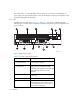
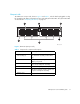
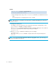
Port side
The MP Router’s port side, shown in Figure 1 and Table 2, includes two 320-watt removable,
redundant power supplies with hot-swappable capability, Fibre Channel ports, management ports,
and a serial port.
Figure 1 MP Router (port side)
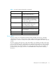
Table 2 Port side component descriptions
Item Summary
1 System status LEDs
Indicate overall system status, including
ports and power supplies
.
2 FC ports
(0 through 15)
Full duplex, auto-sensing of 1- and
2-Gb/s port speeds. MP Router Base
model ships with eight ports activated. MP
Router Full ships with sixteen ports
activated.
3 Port status LEDs
Indicate how particular ports are
functioning.
4 Management ports (2)
Provides Ethernet ports.
5 Serial port
Provides an RJ-45 connector for setting
initial parameters. Connects the console
port on the MP Router to an RS-232 port
on a computer workstation.
0
SPEED
LINK SPEED
ACTIVITY
MGMT2 MGMT1 CONSOLE
FC/GbE
LINK/ACT
POWER
PORTS
SYSTEM
123456789101112131415
DC
OK
AC
OK
100-240 VAC 6.0 A 47-63 Hz
DC
OK
AC
OK
100-240 VAC 6.0 A 47-63 Hz
1 2 3 4
5
6
7 8
9
10
11
12
13
MRO25003a