
HP StorageWorks Multi-protocol Router Installation Guide (A7437-96003, September 2005)


Multi-protocol router installation guide 17
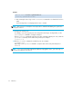
Nonport side
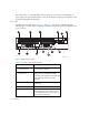
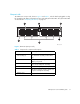
The MP Router’s nonport side, shown in Figure 2 and Table 3, includes dual hot-pluggable cooling
fan assemblies with LEDs (containing three fans each) and system status LEDs. The system status LEDs
are described in ”Interpreting LED activity” on page 51.
Figure 2 MP Router (Nonport side)
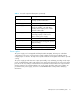
Table 3 Nonport side component descriptions
Item Summary
1 Fan assembly (2)
The chassis contains two fan assembly
slots. Each fan assembly contains three
fans.
2 System status LED
Full duplex, auto-sensing of 1- and
2-Gb/s port speeds.
3 Yellow handle
Pull to release faulty fan assembly.
4 Fan (1 of 6)
Provide cooling for system components.
5 Fan status LEDs
Indicate fan activity or failure. Alerts user
to replace a faulty fan assembly.
6 Captive screw
Remove to detach a failed fan assembly.
FAN OK FAN FAIL
FAN OK FAN FAIL
SYSTEM
PORTS
1
2
3
4
5
6
MRO25004a