
HP StorageWorks Multi-protocol Router Installation Guide (A7437-96003, September 2005)

Multi-protocol router installation guide 35
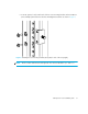
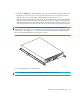
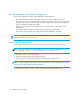
5. For both HP 10000 series and HP System/e racks, use the mounting holes shown in Figure 8 to
attach the two inner rails (one on each side) to the MP Router. Use six screws (three on each
side) of the 8-32 x 5/16-inch Phillips pan-head SEMS screws as shown in Figure 8.
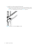
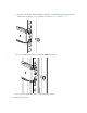
When viewing a rack from the front, the left rails are used in the left side of the rack and the right
rails are used in the right side of the rack. The rails must match up—right inner with right outer
and left inner with left outer. Note that the MP Router mounts in the rack with its front, the port
side, facing the back of the rack. The rear of the router, the AC side, faces the front of the rack.
NOTE: The rail kit provides fourteen #8-32 x 5/16-inch Phillips pan-head SEMS screws for
assembling the inner rails onto HP StorageWorks devices. Each device requires a different number
of these screws. For example, Figure 8 shows an inner rail being attached to the MP Router with
three screws. Attaching both inner rails requires six screws.
Figure 8 Attaching the rails to the MP Router
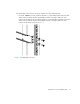
NOTE: This step applies to both the HP 10000 series and HP System/e rack.
0
S
P
E
E
D
L
I
N
K
S
P
E
E
D
A
C
T
I
V
I
T
Y
M
GMT2
MGMT1
CONSOLE
F
C
/
G
b
E
L
I
N
K
/
A
C
T
POWER
PORTS
SYSTEM
1
2
3
4
5
6
7
8
9
10
11
12
13
14
15
D
C
O
K
A
C
O
K
1
0
0
-
2
4
0
V
A
C
6
.0
A
4
7
-6
3
Hz
D
C
O
K
A
C
O
K
1
0
0
-2
4
0
V
A
C
6
.0
A
4
7
-6
3
Hz
MRO25007a