
HP StorageWorks Multi-protocol Router Installation Guide (A7437-96003, September 2005)

Monitoring the MP Router54
Multi-protocol port LEDs
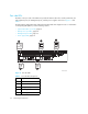
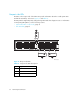
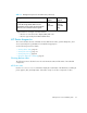
The three LEDs beneath each multi-protocol port, as shown in Figure 11, indicate how that particular
port is functioning. Interpreting the status of an individual port requires the combination of each of
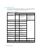
its three LEDs. See Table 11 for a description of the multi-protocol port LEDs.
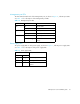
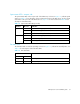
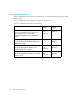
Table 11 Multi-protocol port LEDs
Indication LED label
Link/Act FC/GbE Speed
Default or Configured
foruration indicator
Off Configured for FC
mode = green
Configured for GbE
mode = yellow
Configured for for
auto-negotiate = off
Configured for for fixed
2Gb/s = green
Configured for for fixed
1Gb/s = off
FC receiving light, but not
online
Off Green (continuous) 2Gb/s = green
1Gb/s = off
FC link up, but no traffic Green
(continuous)
Green (continuous)
FC traffic Green
(flashing)
Green (continuous)
FC E_Port segmented 0.5 Hz
Green
(flashing)
0.5 Hz yellow
(flashing)
FC port disabled Off 0.25 Hz yellow
(flashing)
FC port (multiple loop
targets detected when
not permitted)
Green
(continuous)
1 Hz alternating
green/yellow
(flashing)
GbE receiving light, but
not online
Off Yellow (continuous)
GbE link up, but no
traffic
Green
(continuous)
Not applicable
GbE traffic Green
(flashing)
Not applicable
GbE port disabled (not
implemented)
Not
applicable
Not applicable Not applicable
Port error* Off Yellow (continuous) Yellow (continuous)
*NOTE: In this state, the port with problems is signified by yellow (flashing) LEDs.