HP StorageWorks N1200-320 4Gb Network Storage Router user and service guide *AG314-96001* AG314-96001 Part number: AG314-96001 First edition: June 2006
Legal and notice information © Copyright 2006 Hewlett-Packard Development Company, L.P. Hewlett-Packard Company makes no warranty of any kind with regard to this material, including, but not limited to, the implied warranties of merchantability and fitness for a particular purpose. Hewlett-Packard shall not be liable for errors contained herein or for incidental or consequential damages in connection with the furnishing, performance, or use of this material.
Contents About this guide . . . . . . . . . . . . . . . . . . . . . . . . . . . . . . . . . . . . . . . . . . . . . . . . . . . . . . . 7 Intended audience . . . . . . . . . . . . . . . . . . . . . . . . . . . . . . . . . . . . . . . . . . . . . . . . . . . . . . . . . . . Related documentation . . . . . . . . . . . . . . . . . . . . . . . . . . . . . . . . . . . . . . . . . . . . . . . . . . . . . . . . Document conventions and symbols . . . . . . . . . . . . . . . . . . . . . . . . . . . . . . . . . . . .
N1200-320 4Gb Network Storage Router management . . . . . . . . . . . . . . . . . . . . . . . 27 Configuration methods . . . . . . . . . . . . . . . . . . . . . . . . . . . . . . . . . . . . . . . . . . . . . . . . . . . . . Serial port management access . . . . . . . . . . . . . . . . . . . . . . . . . . . . . . . . . . . . . . . . . . . . . Out-of-band Ethernet management access. . . . . . . . . . . . . . . . . . . . . . . . . . . . . . . . . . . . . . Command Line Interface . . . . . . . . . . . . . .
Editing a host . . . . . . . . . . . . . . . . . . . . . . . . . . . . . . . . . . . . . . . . . . . . . . . . . . . . . . . Trace and event settings configuration . . . . . . . . . . . . . . . . . . . . . . . . . . . . . . . . . . . . . . . . Trace configuration . . . . . . . . . . . . . . . . . . . . . . . . . . . . . . . . . . . . . . . . . . . . . . . . . . . Event configuration . . . . . . . . . . . . . . . . . . . . . . . . . . . . . . . . . . . . . . . . . . . . . . . . . . .
A Pin assignments. . . . . . . . . . . . . . . . . . . . . . . . . . . . . . . . . . . . . . . . . . . . . . . . . . . 101 DB-9 pin assignments . . . . . . . . . . . . . . . . . . . . . . . . . . . . . . . . . . . . . . . . . . . . . . . . . . . . . . . . . 101 RJ-45 Ethernet Pin Assignments . . . . . . . . . . . . . . . . . . . . . . . . . . . . . . . . . . . . . . . . . . . . . . . . . . 102 B Regulatory compliance and safety . . . . . . . . . . . . . . . . . . . . . . . . . . . . . . . . . . . . . .
About this guide This guide provides information about: • Installing the HP StorageWorks N1200-320 4Gb Network Storage Router • Configuring the HP StorageWorks N1200-320 4Gb Network Storage Router • Troubleshooting the HP StorageWorks N1200-320 4Gb Network Storage Router Intended audience This guide is intended for general users who need physical and functional knowledge of the HP StorageWorks N1200-320 4Gb Network Storage Router.
IMPORTANT: Provides clarifying information or specific instructions. NOTE: Provides additional information. TIP: Provides helpful hints and shortcuts. HP technical support Telephone numbers for worldwide technical support are listed on the HP support web site: http://www.hp.com/support/.
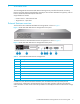
1 Introduction The HP StorageWorks N1200-320 4Gb Network Storage Router provides bi-directional connectivity between one Fibre Channel Switched Fabric (FC-SW) or Fibre Channel Arbitrated Loop (FC-AL), and two Narrow/Wide Fast/Ultra320 LVD/SE SCSI buses. Supported devices include: • Initiator Devices – Fibre Channel hosts • Target Devices – Tape drives External features overview The front of the HP N1200-320 4Gb Network Storage Router is shown in Figure 1.
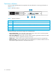
Operation indicators The HP N1200-320 4Gb Network Storage Router has LED indicators for monitoring overall status as shown in Figure 3.
How the HP N1200-320 4Gb Network Storage Router works The network storage router is a device that translates the Fibre Channel Protocol (FCP) to and from the SCSI Protocol—transparently transferring commands, data, and status information—so that both the Fibre Channel (FC) and SCSI devices and hosts can communicate with each other.
External indicators • Fibre Channel link status and activity LEDs • SCSI bus activity LED • Ethernet link status and activity LEDs • Power/Fault LED HP N1200-320 4Gb Network Storage Router benefits The network storage router is designed to connect SCSI devices into a Fibre Channel (FC) fabric or loop. The network storage router comes with one 4 Gb/s Fibre Channel port and two LVD/SE SCSI buses.
2 Installation, cabling, and setup NOTE: Read this chapter carefully and completely before working with the network storage router.
Desktop installation Remove the router from the protective bag. Attach the stick-on feet to the bottom four corners of the router. Place the router on a flat, level table or desktop making sure the airflow vents are clear of obstructions. WARNING! Do not place objects on top of the network storage router. Rack mount installation IMPORTANT: The size of the router and it’s rail assembly is 1U.
Attach the outer rail assembly to the rack NOTE: The size of the router and the rail assembly is 1U. 1. Determine the correct rack location. 2. Align the three screw holes on the front of the outer rail assembly with the front of the rack. All three holes must be exactly aligned. 3. With the outer rail assembly flush against the inside front of the rack, insert two 10-32 x 6 Phillips screws, and tighten. Do not insert a screw in the center hole of the bracket.
Attach the rear extension bracket 1. Loosen the screw on the rear extension bracket of the outer rail assembly. 2. While holding the outer rail assembly level, extend the rear extension bracket to the inside of the rear of the rack. 3. Attach the rear extension bracket to the rear of the rack using two of the 10-32 x 6 Phillips screws. 4. With the outer rail assembly in place, tighten the screw that connects the rear extension bracket to the outer rail. 5.
Install the router into the rack 1. Move the ball-bearing slide on each of the outer rails towards the front of the rack. 2. From the front of the rack, with the front side of the router facing out, align the inner and the outer rails and slide the inner rail into the outer rail. 3. When the rails lock in place, press in the spring latches on each of the inner rails and push the router into the rack.
Setting up serial port communications The network storage router is designed to communicate with a terminal or any operating system utilizing a terminal emulator. For example, most Windows® operating systems can use a terminal. Be sure the baud rate, data bits, stop bits, parity, and flow control are set correctly. To set up serial communications with the network storage router: 1.
Cabling the N1200-320 4Gb Network Storage Router NOTE: Refer to the HP StorageWorks MSL2024 or the MSL4048 Tape Library User and Service Guide for detailed tape library information. Interfaces and connections There are four types of interfaces to the network storage router: • Fibre Channel • SCSI • 3-pin serial port • Ethernet The 3-pin serial and Ethernet ports are used for configuration and management of the network storage router.
SCSI connection CAUTION: SCSI ports on the network storage router are not hot-pluggable. Power off the network storage router whenever connecting/disconnecting the SCSI cables. The network storage router can support Fast/Ultra320 Narrow/Wide SCSI, depending on the specific configuration. The network storage router is factory configured to support LVD/Single-Ended buses. Two VHDCI 68-pin D-shell, P-type connectors are available, allowing the unit to be attached at the end of up to two SCSI buses.
Serial port connection The 3-pin connector on the network storage router provides a serial port that is compatible with RS-232 signaling levels. The network storage router is designed to communicate with a terminal or any operating system using a terminal emulator. The baud rate, data bits, stop bits, parity, and flow control of both the network storage router and the host system must use the same settings.
Installation, cabling, and setup
3 Device management To provide connectivity between hosts and devices, it is necessary for the network storage router to be recognized with an address on the connected Fibre Channel network. SCSI bus configuration The network storage router provides the capability to reset SCSI buses during the network storage router boot cycle. This allows the devices on a SCSI bus to be set to a known state. Configuration provides for the SCSI bus reset feature to be enabled or disabled.
Discovery Discovery is a feature that makes it easy to display attached FC and SCSI target devices and have them mapped automatically on the host side for the connected bus/port. There are two discovery methods available—Manual Discovery and Auto Discovery. Auto Discovery can be set to occur after either reboot events (when the card reboots) or link-up events (for instance, when cables are attached or a hub is rebooted).
• The Indexed map is initially empty and can be modified by the user, however, this is not recommended. • The Auto Assigned map is built dynamically, and contains all the devices found during discovery. This map changes automatically any time the discovery process finds a change in the devices attached to the network storage router. This map can be displayed, but cannot be modified directly by the user. • The SCC map is only available on the FC port and contains a single entry.
Device management
4 N1200-320 4Gb Network Storage Router management The HP N1200-320 4Gb Network Storage Router can be managed over the following user interfaces: • Over the serial port via a terminal or a terminal emulation utility (see ”Setting up serial port communications” on page 18). • Over Ethernet via a Telnet utility or an HTTP-based interface called Visual Manager. Additionally, FTP support provides additional management functionality (see ”Visual manager user interface” on page 31).
Your DHCP server may also allow you to set up an extended lease reservation for an IP address, by providing the server with the Ethernet MAC address of the network storage router. This configures the DHCP server to always provide the same IP address to the network storage router. This setup can be useful for remote management of the network storage router via Telnet.
Visual manager The network storage router allows any standard Internet Web browser to view and change the network storage router’s configuration with the Visual Manager interface. Information is dynamically generated in an HTML format by the network storage router, so that Web browsers can access it. To access Visual Manager, enter the IP address of the network storage router into the Address field of a Web browser.
N1200-320 4Gb Network Storage Router management
5 Visual manager user interface The HP N1200-320 4Gb Network Storage Router allows any standard Internet Web browser to view and change the network storage router’s configuration with the Visual Manager interface. Information is dynamically generated in an HTML format by the network storage router so that Web browsers can access it. To access Visual Manager, enter the IP address of the network storage router into the address field of a Web browser.
5. Enter the authorized user name and password. The user name and password are case-sensitive. The default user name is root and the default password is password. Figure 10 Password dialog box NOTE: HP recommends changing the user name and password from the defaults (see”User name and password” on page 38). NOTE: To end the current session of VM, the browser window must be closed. Navigating the browser to another URL does not end the current session.
Home page The Main menu home page is displayed when Visual Manager (VM) is accessed. The home page contains status information, including a physical image of the network storage router (see Figure 12). Figure 12 Visual Manager Home page Home page information includes: • The HP logo is located in the upper left corner of the Home page. If the Internet is accessible to the host, click the HP logo to open the web site. • An illustration of the network storage router is located near the top of the home page.
• Main menu options: • Home displays network storage router status information. • System configures standard system components. • Ports configures the Fibre Channel port and SCSI buses. • Discovery displays devices and discovers new devices. • Mapping displays and configures maps. • Statistics displays network storage router statistics. • Utilities configures utility settings. • Report displays system information. • Reboot restarts the network storage router.
Serial configuration The Serial screen is used to change the baud rate for the serial port (see Figure 15). NOTE: If the Autobaud feature is being used, it may not be necessary to set the baud rate. Figure 15 Serial screen The current baud-rate setting is displayed. Baud rate choices are: • 9600 • 19200 • 38400 • 57600 • 115200 NOTE: HP recommends setting the baud rate to 115200.
Network configuration The Network screen is used to enter Ethernet configuration settings (see Figure 16). Figure 16 Network screen CAUTION: If this configuration is incorrectly set, processing difficulties may occur. Before changing this setting, evaluate the need for the change and verify the desired setting. HP recommends backing up the network storage router configuration to an external file before making changes to this setting.
NOTE: To use the DHCP feature, a DHCP server must be operational on the Ethernet network. If the DHCP feature is used when there is not a DHCP server, the standard for DHCP requires the network storage router to wait three minutes for a response from a DHCP server before timing out. Some DHCP servers allow an extended lease reservation to be set up for an IP address by providing the server with the Ethernet MAC address. The DHCP server always provides the same IP address to the network storage router.
User security settings User name and password The User screen is used to set up network storage router security such as the user name and password (see Figure 18). Figure 18 User screen User settings: • User Name (default: root) is any alphanumeric combination. • Password (default: password) is any alphanumeric combination. Passwords must be 8 to 11 characters in length. • Confirm Password The user name and password should be unique and kept confidential.
Real-Time Clock configuration The Real-Time Clock screen is used to set the system time and date (see Figure 19). Figure 19 Real-Time Clock screen Date/time settings: • Date Settings sets the month, day, and year (use a four-digit number to represent the year) • Day of Week sets the day of the week. • Time Settings sets the hours, minutes, and seconds. The system clock is a 24-hour clock. There is no a.m. or p.m. designation. Example 1:00 p.m. is 13 hours, 00 minutes.
Reset menu The Reset menu is used to reset the network storage router to factory default settings (see Figure 20). Figure 20 Reset to Factory Default screen Current network storage router activities are disrupted while the unit resets the configuration to the factory defaults and saves those options to FLASH memory. CAUTION: Resetting the network storage router configuration to the factory defaults deletes custom maps or map changes.
Ports menu Accessed from the Main menu, the Ports menu is used to view and to modify configuration settings of the Fibre Channel port and SCSI buses (see Figure 21). Figure 21 Ports menu The initial screen display of the Ports menu includes summary information about each Fibre Channel port and SCSI bus in the network storage router. Ports menu tasks: • Fibre Channel Port 0 configuration changes the Fibre Channel port settings. • SCSI Bus 0, 1 configuration changes SCSI bus settings.
Fibre Channel port configuration When the Fibre Channel port is selected in Ports menu, the Fibre Channel Configuration screen is displayed (see Figure 22). Figure 22 Fibre Channel port 0 configuration settings screen Fibre Channel port settings: • Link Status indicates the port link status. • Port Mode (default: N_Port) sets the port mode. Port Mode settings: • Auto Sense: In this mode, the Fibre Channel port tries to negotiate as a loop.
• Discovery on Link Up allows the network storage router to automatically discover all Fibre Channel devices when rebooted or when link-up events occur, such as connecting cables or rebooting network hubs. • Both the ports and the devices behind the ports are discovered for the first link-up event. Subsequent link-up events only discover the ports and not the devices behind the ports.
SCSI bus configuration When a SCSI bus is selected in the Ports menu, the SCSI Bus Configuration screen is displayed (see Figure 23). Figure 23 SCSI Bus 0, 1 configuration screens SCSI bus configuration settings: • Primary Initiator ID (default: 7) must be a unique ID. • Discovery toggles between Enabled and Disabled, Enabled by default. • Bus Reset on Boot toggles between Enabled and Disabled.
Discovery menu Accessed from the Main menu, the Discovery menu is used to view existing, and discover new Target devices (see Figure 24). Figure 24 Discovery screen To perform a manual discovery: 1. Select the Fibre Channel port or SCSI bus from the menu bar or the network storage router image. 2. Select Go.
Figure 26 Perform discovery on SCSI Bus 0 screen 46 Visual manager user interface
Mapping menu Accessed from the Main menu, the Mapping menu is used to create or edit LUN maps and assign them to hosts. (see Figure 27). Figure 27 Mapping screen NOTE: Indexed, Auto Assigned, and SCC maps cannot be deleted or renamed. NOTE: SCC and Auto-Assigned maps cannot be cloned.
Viewing and changing Fibre Channel map information NOTE: Port 0 Device Map is the HP recommended map to be used for editing and assigning to hosts that communicate with the library. The Indexed (default) map should not be used for editing, even though the user is able to edit this map. To view or change current Fibre Channel map information: 1. In the Mapping menu screen, select the desired map. 2. Select Edit/View in the Map section of the screen. The Fibre Channel Map dialog box is displayed.
Statistics menu Accessed from the Main menu, the Statistics menu is used to display Fibre Channel port and SCSI bus information (see Figure 28). Figure 28 Statistics menu To view information for a specific port or bus, click the component on the menu bar or the network storage router image. To refresh the display, select Reset FC & SCSI System Statistics.
Utilities menu Accessed from the Main menu, the Utilities menu is used to view and configure utility options (see Figure 29). Figure 29 Utilities menu Utilities menu tasks: • FTP Utility opens an FTP session. • Trace Settings configures trace settings. • Current Traces displays current trace information. • Previous Traces displays previous trace information. • Last Assert Traces displays last assert trace information. • Clear Current Traces clears current trace information.
FTP utility access The FTP utility screen is used to open an FTP session (see Figure 30). Figure 30 FTP Utility screen The FTP utility requires the use of a JAVA applet and prompts for permission to install the applet, if needed. If the prompt is displayed, follow the on screen instructions to complete the installation. The FTP utility then prompts for permission to run the applet.
NOTE: If a valid firmware or configuration file is uploaded to the network storage router, an automatic reboot occurs once the file has been received. The network storage router cannot be accessed from the Visual Manager UI during the time that the reboot is in process, which is approximately 30 seconds. Trace settings configuration This menu allows the configuration of Trace Settings (see Figure 31).
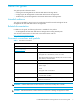
Table 5 Trace Settings Setting Description INBAND Controller management functionality is monitored and recorded Queue Element Debugging capability for specific network storage router resources Current, previous, and last assert trace displays These three Utilities menu screens show trace information. • The Current Traces screen shows data since the network storage router was last booted. • The Previous Traces screen shows data from the last boot cycle.
• Warning Events • Notify Events • Info Events • Debug Events • Log All Events Event logging captures the last 215 events and then starts overwriting the log. NOTE: To correlate event logging, correctly set the clock and date in the Real-Time Clock configuration menu (see ”Real-Time Clock configuration” on page 39). Event log display The Event Log screen is used to view the Event Log (see Figure 33).
Clear event log The Clear Event Log screen is used to clear the Event Log (see Figure 34). Current network storage router activities are not disrupted. Figure 34 Clear event log screen SCSI command tracking This menu provides options for setting up and logging SCSI commands that are received or transmitted by the network storage router. Results are displayed in the Host/Device ID Table (see Figure 35).
While the network storage router’s current, previous, and last assert trace data does provide a complete summary of events in a chronological fashion, SCSI Command Tracking adds the ability to filter the trace data to show only the information related to the processing of specific SCSI commands. • SCSI Command Tracking can be toggled to ON or OFF.
Reboot option CAUTION: Confirm there is no activity, such as a backup in progress, before initiating a reboot because network storage router activities will be disrupted. Network storage router reboots are executed using this Main menu option (see Figure 36). When the library is rebooted, current network storage router activities are disrupted. All submitted configuration changes are activated during the boot-up process.
Visual manager user interface
6 Using the Command Line Interface This chapter describes specific configuration options available from the perspective of the Command Line Interface (CLI). For an overview of using the other configuration methods available, see ”N1200-320 4Gb Network Storage Router management” on page 27. The network storage router allows the user to access many configuration settings through the Command Line Interface.
The main menu allows for various operations to be performed on the network storage router. • Select 1 to access network storage router configuration settings. • Select 2 to access System Utilities. • Select 3 to display trace and assertion history. • Select 4 to reboot the network storage router. A confirmation message appears to verify this action. • Enter N to return to the System Utilities menu. • Enter Y to restart the network storage router. • Select 5 to download a new revision of the firmware.
Baud rate configuration This menu changes the baud rate used on the serial port. Select 1 through 5 for the appropriate baud rate setting. If you are using the Autobaud feature, it may not be necessary to set a baud rate. See ”Autobaud feature” on page 21 for more information on using the Autobaud feature. The default setting for the baud rate is 115200. Figure 39 Baud rate configuration menu Baud Rate Configuration Menu X.XX.
Ethernet configuration This option allows for setting up all Ethernet network settings including IP address, subnet mask, IP gateway, security settings, Ethernet mode, physical address, and host name. Figure 40 Ethernet configuration menu Ethernet Configuration Menu X.XX.XX XXXXXX 07/7/2005 XXXXXXXXXXXXXXXX 08:56:22 IP Address : 192.168.60.203 [DHCP] Subnet Mask : 255.255.255.0 IP Gateway : 192.168.60.
• Select 7 to toggle the DHCP setting. This setting enables/disables support for Dynamic Configuration Protocol. The default setting is enabled. When enabled, the network storage router retrieves a dynamic IP address from a DHCP server located on the Ethernet network that the network storage router is connected to. If DHCP is disabled and then enabled, it is necessary to save the current configuration and reboot the network storage router before an IP address can be requested from the DHCP server.
Fibre Channel configuration This menu allows for setting the Fibre Channel Address method, Hard Address value, discovery mode, WWN overrides, tape backup settings, default map value, and FC port mode. Figure 41 Fibre Channel configuration menu Fibre Channel Configuration Menu X.XX.
• Select 3 to change the Toggle Port Mode between Auto Sense - Soft AL_PA, N_Port, and Auto Sense Hard AL_PA. The default setting is N_Port mode. In this mode, the FC port tries coming up as a fabric port. If the network storage router is on a loop and N_Port mode is selected, an error in communication may occur. In Autosense - Soft AL_PA mode, the network storage router FC port tries to come up as a loop, and if not successful, then tries to come up as a fabric.
Following are descriptions for each of the override settings: NOTE: Normally, override settings should not be changed except when directed to do so by an authorized HP technician. • Select 1 to toggle the Hi-Sup Bit between SET and CLEAR. The default setting is CLEAR. This option should be toggled to SET when the server uses the Hi-Sup bit to scan for FC LUNs greater than eight. NOTE: Hi-Sup Bit is only set in an Active Fabric LUN which needs to be mapped as the first device (FC LUN 00).
Parallel SCSI configuration This menu allows for setting up SCSI attributes. Figure 42 Parallel SCSI configuration menu Parallel SCSI Configuration Menu X.XX.
SCSI initiator menu This option allows for setting up the SCSI Initiator. Figure 43 SCSI initiator menu SCSI Initiator Menu X.XX.XX XXXXXX 07/7/2005 XXXXXXXXXXXXXXXX 08:56:22 Current Initiator Configuration - Bus 0 Initiator ID : 07 1) Select primary SCSI Initiator ID 2) Enable/Disable alternate SCSI ID (The "alternate" ID is used to enhance the performance of status ("agent") commands that are being issued to a serial device.
Maximum SCSI bus speed menu This option allows for setting the maximum SCSI bus speed. When this option is selected, the user must first select the Target ID for the bus before this menu appears. Figure 44 SCSI bus speed configuration menu SCSI Bus Speed Configuration Menu X.XX.
Device mapping This option allows the user to manipulate maps and associate a selected host with a particular map. Each physical port/bus on the system has at least an Indexed map and an Auto Assigned map. In addition, there is a SCC Map and a Port 0 Device Map on FCP ports. Each map has a unique name and map ID. You can rename all maps, except for Indexed, Auto Assigned, and SCC.
NOTE: Because the entire list of maps may not fit on one screen, select N or P to go back and forth between screens displaying more maps. Select X to return to the Device Mapping Main menu. • Select 3 from the Device Mapping Main menu to create a new map. This option allows adding a new map for the current protocol/port or bus. Once the map is created, it becomes the current map. • Select 4 from the Device Mapping Main Menu to delete current map. The screen asks for confirmation before deleting the map.
NOTE: Hi-Sup Bit is only set in an Active Fabric LUN which needs to be mapped as the first device (FC LUN 00). Select a number from the left column Num to add a device to the map. Selecting a device where LUN=’-’ adds all LUNS for this target. If the selected device is already mapped, an error message appears to warn the user about adding a duplicate device. N and P controls allow scrolling up and down the device list. X brings the user back to the Edit Map Entries display table.
Remove gaps NOTE: SCSI devices attached to a Fibre Channel port must be mapped as sequential FC LUNs starting at LUN number 00. Skipping LUN numbers is not recommended when mapping FC LUNs because FC Discovery stops the discovery process whenever an empty LUN position is found. This option removes any incremental gaps in the sequence of LUNs listed in the table. Deleting an entry The user selects a LUN ID.
The following is an example of a host list for FCP hosts: Figure 49 Host list for FCP hosts Host List Edit Display X.XX.
Following the successful addition of the host, the host list is displayed again and the user can make sure that the host information is correct. Deleting a host Select D to delete a host from the host list. The operator is asked to enter an index for the host that is displayed in the very left column of the table, and asked for confirmation. Editing a host Select E to edit host information.
• Select 8 from the Device Mapping Main menu to display the entire device list. Because the entire device list may not fit on one screen, select N or P to go back and forth between screens displaying more maps. Select X to return to the Device Mapping Main menu. Figure 52 Entire device list Entire Device List X.XX.
Trace and event settings configuration This option allows set up of trace and events settings. Figure 53 Utility settings Utility Settings X.XX.XX XXXXXX XXXXXXXXXXXXXXXX 07/7/2005 08:56:22 1) Trace Settings Configuration 2) Event Settings Configuration 3) Special Event Logging Configuration X) Return to previous menu • Select 1 to edit the trace settings configuration. • Select 2 to edit the event settings configuration. • Select 3 to edit the special event logging configuration.
If the Enter key is selected, the next page of trace levels appears as follows: Figure 55 Trace settings Trace Settings X.XX.XX XXXXXX 07/7/2005 0) SG List : OFF 1) Timing : OFF 2) FCP/RMI : OFF 3) AF : OFF 4) INBAND : OFF 5) Multi-Host Lib : OFF 6) Queue Element : OFF XXXXXXXXXXXXXXXX 08:56:22 U) Update Current Operating Trace Levels X) Return to previous menu Enter the trace level index, for next page > Enter a level number from the Trace Settings that are shown.
• Enter 1 to disable event logging. • Enter 2 through 9 to log the specified events or higher. • Enter 0 to log all events. • Select U to send event configuration changes to the network storage router now. NOTE: Event logging captures over 2000 events and then starts overwriting the log when full. NOTE: Be sure to correctly set the clock and date in the Real-Time Clock Configuration menu so that event logging is accurate.
Real-Time clock configuration When this option is selected from the Perform Configuration menu, the System Clock Setup menu appears. NOTE: The time is based on a 24-hour clock. There is no a.m. or p.m. designation. For example: 1:00 p.m. is 13 hours 00 minutes or 13:00. Figure 58 System clock setup menu - System Clock Setup Menu X.XX.XX XXXXXX XXXXXXXXXXXXXXXX 07/7/2005 08:56:22 TUESDAY, Date: 07/7/2005, Time: 08:56:22 1) Set clock X) Return to previous menu Select 1 to set the clock.
• Select 2 to change the location of LUNs in an auto-assigned map. LUNs can be positioned starting at the beginning (first location) or at the end (last location) of the map. NOTE: Controller LUNS in auto-assigned map settings are First or Last. Setting the choice to Last is recommended. Setting the choice to First can cause issues with HP-UX. However, if working with an OVMS host, it should be set to First. For more information on network storage router LUNs, see ”Inband SCSI-3 commands” on page 109.
System statistics menu Figure 61 System status/statistics menu System Status/Statistics menu X.XX.XX XXXXXX 07/7/2005 XXXXXXXXXXXXXXXX 08:56:22 1) Display System Status 2) Display Fibre Channel Protocol Status 3) Display Parallel SCSI Protocol Status X) Return to main menu • Select 1 from the System Status/Statistics menu to display system status. Figure 62 System status menu System Status Menu X.XX.
• Select 1 from the Fibre Channel Status menu to display Fibre Channel Link Status. Figure 63 below shows the status and statistics for a Fibre Channel loop. Similar data can also be shown for a Fibre Channel fabric. Figure 63 Fibre Channel status menu Fibre Channel Status & Statistics X.XX.
Table 6 Fibre Channel status SyncLosses is the number of times loss of sync. was detected. BadRxChars is the number of bad characters received. LinkFailures is the number of link failure conditions. BadCRCFrames is the number of frames received with a bad CRC. ProtocolErrs is the number of protocol errors detected. BadSCSIFrames is the number of bad SCSI frames detected. UnderflowErrs is the number of underflow errors detected. Select A to have the status information repeatedly refreshed.
• Select 5 to display FC SeqCmd_Q Resources. • Select 6 to display FC SFP Data. • Select 3 from the System Status/Statistics menu to display Parallel SCSI Protocol Status. Figure 65 Parallel SCSI protocol status menu Parallel SCSI Protocol Status menu X.XX.XX XXXXXX XXXXXXXXXXXXXXXX 07/7/2005 08:56:22 1) Display SCSI Statistics 2) Display Attached SCSI Devices 3) Display SCSI Resource Status X) Return to previous menu • Select 1 to display SCSI statistics. • Select 2 to display attached SCSI devices.
Event Log When this option is selected from the System Utilities menu, the Event Log menu is displayed (see Figure 67). Figure 67 Event log menu Event Log Menu X.XX.XX XXXXXX XXXXXXXXXXXXXXXX 07/7/2005 08:56:22 1) Display event log 2) Clear event log X) Return to previous menu • Select 1 to display the event log. • Select 2 to clear the event log of all old entries and start over with an empty list.
Diagnostics mode When this option is selected from the System Utilities menu, a confirmation message appears to verify the selection. If a response of Y (yes) is given to the confirmation message, current network storage router activities are interrupted while the unit restarts itself and enters diagnostics mode. The power-up messages appear followed by the diagnostics menu (see Figure 69). Figure 69 System diagnostics mode System Diagnostics Mode X.XX.
Special Fibre Channel link control When this option is selected from the System Utilities menu, the Special Fibre Channel Link Control menu is displayed (see Figure 70). Figure 70 Special FC Link states menu Special FC Link Control X.XX.
or other ID. SCSI commands which have already been tracked, then that information is displayed by selecting this option. • Select 4 to clear the log of all previously recorded results. Display trace and assertion history When this option is selected from the main menu, the Trace Dump menu is displayed (see Figure 72). Trace options are set up in the Trace Settings Configuration menu. Figure 72 Trace dump menu Trace Dump Menu X.XX.
• For the previous trace buffer, use get prvtrace.txt. The file transfers from the network storage router. Reboot When this option is selected, a confirmation message appears to verify the selection. If a response of Y (yes) is given to the confirmation message, current network storage router activities are disrupted while the unit restarts itself. The last saved configuration changes also take effect after the network storage router powers on again.
7 Using the FTP interface This chapter describes specific management options available from the FTP interface. For an overview of using the other management interfaces available, see ”N1200-320 4Gb Network Storage Router management” on page 27. Backup/restore configuration settings The network storage router supports backup and restore of configuration settings over FTP.
NOTE: If the network storage router is to use a static IP address, the pre-filled in address when DHCP is disabled is 1.1.1.1 and should be changed to an address that is appropriate for the IP network it will reside on. 3. Enter the user name and password. The default values for user name and password are root for the user name and password for the password. 4. Specify binary mode: bin 5. Specify the configuration’s path and filename (.cfg file) with the put command: put
• For the current event log, use get eventlog.txt. The file will transfer to the current directory specified on your computer’s FTP utility. If running FTP from a DOS or Linux command line, the destination directory can be set using the lcd command (ex. lcd c:\myCfg). Updating firmware Using the following procedure, FTP can be used to update the network storage router firmware. 1. Connect the network storage router to the Ethernet network used by your computer. 2.
Using the FTP interface
8 Troubleshooting Various problems can arise when configuring and using the HP N1200-320 4Gb Network Storage Router. This section is provided to help guide the user through some of the basic methods of identifying faults in the setup and configuration of the network storage router. Most problems are found in the initial installation. In general, it is wise to check all connections and review the configuration before proceeding with further trouble analysis.
corresponding target device activity, there may be a problem with the SCSI bus configuration. Verify the SCSI bus configuration. • Ethernet (10/100)—The LNK should stay permanently lit to indicate an Ethernet link. The ACT indicator should flash to indicate activity. If either of these indicators fail to flicker, or stay continuously lit, there may be a problem with the network connection or configuration. Verify the network connection and configuration.
discovered” device every time there is a reboot. By using the included INF file, the user just needs to identify the network storage router to the Windows Device Manager only once. To install (or register) the network storage router to a connected host Windows PC, perform the following steps: 1. Copy the INF file to the Windows PC which has the FC HBA to be connected to the network storage router.
Even if the SCSI devices are displayed, they are not accessible unless the mapping mode is auto-assigned or another non-empty map is used. Verify Fibre Channel connection If SCSI devices are recognized on the SCSI buses, but do not appear to the Fibre Channel host, it may be that the Fibre Channel link is not properly established. Most hubs and switches have link indicators, showing link status.
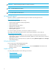
Table 8 HP N1200-320 4Gb Network Storage Router PRLI response data Item Value PRLI Command Code 0x20 Page Length 0x10 Payload Length 0x10 Type Code 0x8 Type Code Extension 0x0 OPA 0x0 RPA 0x0 IPE 0x1 Response Code 0x1 Originator Process Associator 0x0 Responder Process Associator 0x0 Initiator Function 0x1 Target Function 0x1 Command/Data Mixed Allowed 0x0 Data/Response Mixed Allowed 0x0 Read XFER_RDY Disabled 0x1 Write XFER_RDY Disabled 0x0 Verify HBA device driver infor
Troubleshooting
A Pin assignments DB-9 pin assignments In conjunction with the pin assignments provided for the 3-pin receptacle on the rear panel of the HP N1200-320 4Gb Network Storage Router, following are the corresponding pin out assignments for a DB-9 serial connector used to connect the other end of the serial cable to a terminal, or a computer running terminal emulation software. The pin assignments given in Figure 75 for the DB-9 serial connection are in reference to the serial connector at the end of the cable.
RJ-45 Ethernet Pin Assignments The pin assignments given for the RJ-45 Ethernet connection are in reference to the Ethernet receptacle on the back panel of the HP N1200-320 4Gb Network Storage Router. The HP N1200-320 4Gb Network Storage Router Ethernet connection supports the IEEE specifications for 10BASE-T and 100BASE-TX Ethernet standards.
B Regulatory compliance and safety Regulatory compliance Regulatory compliance identification numbers For the purpose of regulatory compliance certifications and identification, your product has been assigned a unique Regulatory Model Number. The RMN can be found on the product nameplate label, along with all required approval markings and information. When requesting compliance information for this product, always refer to this RMN.
• Connect the equipment into an outlet on a circuit that is different from that to which the receiver is connected. • Consult the dealer or an experienced radio or television technician for help. Declaration of conformity for products marked with the FCC logo, United States only This device complies with Part 15 of the FCC Rules.
International notices and statements Canadian notice (avis Canadien) Class A equipment This Class A digital apparatus meets all requirements of the Canadian Interference-Causing Equipment Regulations. Cet appareil numérique de la classe A respecte toutes les exigences du Règlement sur le matériel brouilleur du Canada. Class B equipment This Class B digital apparatus meets all requirements of the Canadian Interference-Causing Equipment Regulations.
Japanese notice Korean notices Safety Battery statement WARNING! This product contains one lithium manganese dioxide battery. • The N1200-320 4Gb Network Storage Router contains one Snaphat® lithium battery. • The lithium battery is located in the upper left corner of the board, is yellow in color, and can be removed with a flat blade screwdriver. Lithium may be considered a hazardous material. Dispose of these batteries in accordance with local, state, and federal laws.
Taiwan battery recycling notice The Taiwan EPA requires dry battery manufacturing or importing firms in accordance with Article 15 of the Waste Disposal Act to indicate the recovery marks on the batteries used in sales, giveaway or promotion. Contact a qualified Taiwanese recycler for proper battery disposal.
Regulatory compliance and safety
C Inband SCSI-3 commands The HP N1200-320 4Gb Network Storage Router supports a set of SCSI-3 commands that can be received inband over FCP. When received by the network storage router, these commands are then executed by the network storage router itself. When using SCSI-3 commands to access general management features, the commands can be sent to device LUNs that are mapped through the network storage router. The following is a list of the SCSI-3 commands that are supported by the network storage router.
The network storage router returns the LUN Parameters as defined in Table 12. Table 12 Report LUNs Parameter List Bit 7 6 5 4 3 2 1 0 Byte 0 (MSB) 1 LUN list length 2 3 (LSB) 4 Reserved 5 Reserved 6 Reserved 7 Reserved LUN list 0-7 First LUN : 0-7 Last LUN NOTE: The LUN list length is the number of LUNs times 8. All LUNs are reported and will appear in the host’s map. Inquiry command The format of the Inquiry command is shown in Table 13.
EVPD Page 0x80 If the EVPD bit is set and the Page Code is 0x80 the unit serial number page is returned. The format of this page is shown in Table 14. Table 14 Format of EVPD Page 0x80 Bit 7 6 5 4 3 2 1 0 Byte 0 Device Type (0ch) 1 Page Code (80h) 3 Reserved 4 Page Length 5...20 Serial Number The serial number field is a 16-byte left-justified ASCII string.
NOTE: The Revision Level comes from the last four characters of the build string, which appears in the headings for most menu screens.
D Addressing, structures, and operations Fibre Channel and SCSI systems employ different methods of addressing devices. The inclusion of a network storage router requires that a method of translating device IDs be implemented so that each SCSI device is mapped to the appropriate Fibre Channel LUN. The SCSI buses establish bus connections between devices. Targets on a SCSI bus may internally address logical units. The addressing of a specific SCSI device is represented by the BUS:TARGET:LUN triplet.
The network storage router supports the Peripheral Device Addressing Method and the Logical Unit Addressing Method, depending on the configuration.
Indexed addressing option Indexed Addressing allows for host bus adapter (HBA) drivers that only use Peripheral Device addressing to access SCSI devices attached to the network storage router. This is done by use of a table, which is indexed by sequential LUN values, indicating selected BUS:TARGET:LUN devices. It is not possible in this mode to address the network storage router as an network storage router unit directly. The table has the structure as shown in Table 21.
attached devices directly without having to perform discovery by issuing commands through all possible combinations.
E Enabling DHCP on the HP N1200-320 4Gb Network Storage Router DHCP, or Dynamic Host Configuration Protocol, is an open industry standard that simplifies administering networks based on Transmission Control Protocol/Internet Protocol (TCP/IP). DHCP allows network resources to go farther by enabling a unique IP address to be assigned to a specific device (network storage router, client host, etc.) on a non-permanent, dynamic basis.
Setting up DHCP over network storage router interfaces Network storage routers use three different interfaces which can be used to enable DHCP: Serial, Telnet, and VM. The following will describe how to enable and disable DHCP for each interface. NOTE: Located on the network storage router is a label that displays the unit’s Ethernet MAC Address. A network administrator can then use this MAC Address to set up a lease reservation on the DHCP server for the IP address of the network storage router.
• Select 2. The following menu appears: Figure 79 Ethernet configuration menu Ethernet Configuration Menu X.X.XX XXXXXX XXXXXX-XXX_XXXXXXXXXXXXXX 07/7/2005 08:56:22 IP Address : 1.1.1.1 Subnet Mask : 255.255.255.0 IP Gateway : 0.0.0.
DHCP has been successfully activated. Note that the IP Address my also appear different than the former non-DHCP IP Address. NOTE: To use the DHCP feature, a DHCP server must be operational on the Ethernet network used by the network storage router. If the DHCP feature is used when there is no DHCP server, the standard for DHCP requires that the network storage router wait three minutes for a response from a DHCP server before timing out.
Visual Manager To access the network storage router using the Visual Manager interface: 1. Look up the current IP address within the Ethernet Configuration menu using the serial interface. 2. Type the IP address in the Web browser without using “www” or “/” or any other characters or symbols. 3. After entering the IP address, the user should see the Configuration Main menu. Click on the Configuration link. This will access the Configuration Menu containing CURRENT/NEW readings for DHCP (“Use DHCP”).
Enabling DHCP on the HP N1200-320 4Gb Network Storage Router
Glossary adapter A printed circuit assembly that translates data between the FC host processor’s internal bus and a different bus, such as SCSI. address See SCSI addressing. addressing mode Used to create a mapping table that maps devices on the SCSI bus to Fibre Channel logical units. AL_PA Arbitrated Loop Physical Address. A unique one-byte valid value, derived and used in an Arbitrated Loop Topology as defined in ANSI specification FC_AL ver 4.5.
FC device A device that uses Fibre Channel communications. FC port An opening at the back of the network storage router that provides a fiber optic connection between the FC adapter and the FC host. FC-SCSI hardware path ID A FC term describing a list of values showing the physical hardware path of the FC host to the target device. Format: Bus_Converter/Adapter_Address.Protocol_Type.Area.Port.Bus.Target.LUN Example: 8/4.8.0.0.2.4.
initiator A device (usually a host system) that requests an operation to be performed by another device known as a target (usually a peripheral). initiator mode Configuration mode of the network storage router in which a Fibre Channel initiator requests operations to be performed by a SCSI target device.
online For the network storage router, online indicates that at least one adapter in the network storage router is active and available for access. For a SCSI adapter, online indicates the SCSI adapter is active and available for access and input/output processing. For a FC adapter, online indicates the FC adapter is active and available for access and input/output processing. originator The Fibre Channel N_Port responsible for starting an exchange. A FC originator is comparable to a SCSI initiator.
SCSI bus The means of transferring SCSI data between SCSI devices. It is an 8-bit or 16-bit bus that supports up to eight or sixteen devices (including itself), in any mix of initiators and targets, with the limitation that at least one initiator and one target must be present. SCSI device A single unit on the SCSI bus, identifiable by a unique SCSI address. A SCSI device can act as an initiator or target. For SCSI-3, each SCSI device supports up to sixteen LUNs.
Index A addressing 113 audience 7 authorized reseller, HP 8 autobaud 21 Avis Canadien, regulatory compliance notice 105 power-up messages 59 conventions document 7 text symbols 7 current map, default Fibre Channel Visual Manager 43 B D batteries Taiwan EPA recycling and disposal 107 baud rate configuration Visual Manager 35 BSMI, regulatory compliance notice 105 buffered tape writes Fibre Channel Visual Manager 43 bus reset on boot Visual Manager 44 C cables FCC compliance statement 104 shielded 104 Ca
Class B Equipment, compliance notice 103 declaration of conformity 104 modifications 104 Fibre Channel hosts viewing and changing Visual Manager 48 Fibre Channel maps editing entries Visual Manager 48 viewing and changing Visual Manager 48 Fibre Channel port buffered tape writes Visual Manager 43 configuration Visual Manager 42 configuration screen, illustrated 42 default map Visual Manager 43 discovery mode Visual Manager 42 performance mode Visual Manager 43 port mode Visual Manager 42 firmware download 9
Visual Manager 42 R rack stability, warning 8 reboot 90 rebooting Visual Manager 57 recycling, Taiwan EPA battery 107 regulatory compliance information number 103 notices BSMI 105 Canada 105 Class A 103 Class B 103 European Union 105 HP series number 103 IEC EMC statement, worldwide 105 Japan 106 Korean 106 lasers 104 modifications 104 shielded cables 104 related documentation 7 RFI/EMI connector hoods 104 S SCSI bus bus reset on boot Visual Manager 44 configuration of Visual Manager 44 discovery settings
configuration of 42 default map 43 discovery mode 42 hard AL_PA 42 link status 42 performance mode 43 port mode 42 Fibre Channel hosts, viewing and changing 48 FTP access 51 FTP utility screen, illustrated 51 home page 33 home page, illustrated 33 I/O configuration 41 Main menu 33 Main menu, illustrated 33 mapping tasks, Fibre Channel viewing and changing 48 network configuration 36 Network menu options 36 network screen, illustrated 36 Ports menu, illustrated 41 reboot option 57 reboot screen, illustrated