March, 2003 hp storage Installation guide for the b3000 v1 technical white paper table of contents This guide will provide the steps necessary to install and configure a StorageWorks NAS b3000 v1. This guide uses Quick Restore version 2.12 for the b3000.
[Enter your Document Title] [Document Restriction Notice] Creating a Virtual Server with Terminal Services Creating Cluster File Share Resources with the WEBUI Creating Cluster File Share Resources with Terminal Services 26 27 27 2
[Enter your Document Title] [Document Restriction Notice] Introduction This paper will provide a step-by-step process for the installation and configuration of the b3000 v1. It is assumed that the installation will be preformed on a new unit or a unit that has just been quick restored. Additional information about any of the topics covered in the document can be located in the Administration guides for the respective products. Quick Restore The NAS b3000 v1 Quick Restore CD should be labeled version 2.
[Enter your Document Title] [Document Restriction Notice] network. NOTE: The RapidLaunch utility will refresh periodically looking for new devices on the network. You may refresh the device list manually by selecting the Refresh button. 9. Select the unconfigured StorageWorks NAS device from the device list. This launches the WebUI configuration application (Rapid Startup) on the target StorageWorks NAS device. 10. Follow the instructions on the screen to input the correct information.
[Enter your Document Title] [Document Restriction Notice] Configuring and Updating the System NOTE: In a cluster configuration, from this point forward, the first node will be referred to as NODE A and the second node will be referred to as NODE B. The Rapid Launch utility allows an administrator to configure the nodes network configurations from a client before the Quick Restore process. The configuration is saved to a floppy, which may be inserted into the node during the Quick Restore process.
[Enter your Document Title] [Document Restriction Notice] NOTE: Make sure to run the Rapid Startup Utility on both nodes before continuing 5
[Enter your Document Title] [Document Restriction Notice] SAN Connection Tool The SAN Connection Tool is a utility which configures the nodes for connection to a StorageWorks SAN. The SAN Connection tool is accessible through the WEBUI and must be completed after the Rapid Startup utility. No Fiber cables should be connected to the node at this time and the nodes should remain unconnected until after the SAN Connection Tool process is completed.
[Enter your Document Title] [Document Restriction Notice] 12. Rename the file Sdapi.dll to Sdapi.dll.bak. 13. Copy the file "C:\CP002829\Sdapi.dll to the directory "C:\Winnt\System32." 14. Browse to "C:\Program Files\Compaq\SANWorks Virtual Replicator 2.5." 15. Rename the file Sdapi.dll to Sdapi.dll.bak. 16. Rename the file VRRegMon.exe to VRRegMon.exe.bak. 17. Copy the file "C:\CP002829\Sdapi.dll to the directory "C:\Program Files\Compaq\SANWorks Virtual Replicator 2.5." 18.
[Enter your Document Title] [Document Restriction Notice] Installing Cluster Services This section is for installing and configuring cluster services. If the b3000 is not to be part of a cluster, skip this section. It is possible to configure cluster services remotely through the WEBUI using the Cluster Setup Tool. To access the Cluster Setup Tool open an Internet Explorer session from the remote client and navigate to http://hostname:3201.
[Enter your Document Title] [Document Restriction Notice] be accomplished through selective storage presentation, SAN switch zoning or having only one node online at all times. • All software components listed in the SAN connection tool must be installed and the fiber cables attached to the HBA(s) before the cluster installation is started. • All shared disks, including the quorum disk, must be accessible from both nodes.
[Enter your Document Title] [Document Restriction Notice] Note: Do not let both nodes access the shared storage devices at the same time until the Cluster service is installed on at least one node and that node is online. This can be accomplished through selective storage presentation, SAN switch zoning or having only one node online at all times.
[Enter your Document Title] [Document Restriction Notice] (http://support.microsoft.com/support/kb/articles/Q242/4/30.ASP) should be followed and the node rebooted prior to installing the Cluster service. If this procedure is not completed, and the second node is powered off while installing the Cluster service on the first node, the private network adapter may not be detected. This will prevent configuring the adapter during the Cluster service installation.
[Enter your Document Title] [Document Restriction Notice] • Create a small partition [A minimum of 50 megabytes (MB) to be used as a quorum disk. We recommend a quorum disk have at least 1GB of free space.] • Dedicate a separate disk resource for a quorum disk. As the failure of the quorum disk would cause the entire cluster to fail, it is strongly recommended that the disk resource be a RAID 1 configuration. During the Cluster service installation, a drive letter must be provided for the quorum disk.
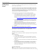
[Enter your Document Title] [Document Restriction Notice] Figure 7. Hardware Configuration Certification Screen 7. Because this is the first node in the cluster, the cluster must be created. Select the first node in the cluster, as shown in Figure 8 below and then click Next.
[Enter your Document Title] [Document Restriction Notice] Figure 8. Create New Cluster 8. Enter a name for the cluster (up to 15 characters), and click Next. (In our example, we name the cluster MyCluster.) 9. Type the user name and password of the cluster service account that was created during the pre-installation. Type the domain name, and click Next. At this point the Cluster Service Configuration Wizard validates the user account and password. 10. Click Next.
[Enter your Document Title] [Document Restriction Notice] In production clustering scenarios more than one private network for cluster communication must be used to avoid having a single point of failure. Cluster service can use private networks for cluster status signals and cluster management. This provides more security than using a public network for these roles. It is possible to use a public network for cluster management, or use a mixed network for both private and public communications.
[Enter your Document Title] [Document Restriction Notice] Figure 10. Public Network Connection 17. The next dialog box shown in Figure 11 configures the private network. Make sure that the network name and IP address correspond to the network interface used for the private network. 18. Check the box Enable this network for cluster use. 19. Select the option Internal cluster communications only.
[Enter your Document Title] [Document Restriction Notice] Figure 11. Private Network Connection 20. Click Next. 21. In this example, both networks are configured in such a way that both can be used for internal cluster communication. The next dialog window offers an option to modify the order in which the networks are used. Because Private Cluster Connection represents a direct connection between nodes, it is left at the top of the list.
[Enter your Document Title] [Document Restriction Notice] Figure 12. Cluster IP Address The Cluster Service Configuration Wizard shown in Figure 12 automatically associates the cluster IP address with one of the public or mixed networks. It uses the subnet mask to select the correct network. 23. Click Finish to complete the cluster configuration on the first node.
[Enter your Document Title] [Document Restriction Notice] Figure 13. Cluster Administrator If your snap-in window is similar to that shown above in Figure 13, your Cluster service was successfully installed on the first node. It is now possible to install the Cluster service on the second node. Configuring the Second Node Note: For this section, leave the first node on and power up the second node. Installing Cluster service on the second node requires less time than on the first node.
[Enter your Document Title] [Document Restriction Notice] 4. Enter the password for the account (if there is one) and click Next. 5. At the next dialog box, click Finish to complete configuration. 6. The Cluster service will start. Click OK. 7. Close Add/Remove Programs. Verify Installation There are several ways to verify a successful installation of Cluster service. Here is a simple one: 1. Click Start, click Programs, click Administrative Tools, and click Cluster Administrator. Figure 14.
[Enter your Document Title] [Document Restriction Notice] Congratulations. You have completed the installation of Cluster service on both nodes. The server cluster is fully operational.
[Enter your Document Title] [Document Restriction Notice] Upgrading SWVR and SFU to be cluster aware For cluster configurations, the Virtual Replicator and Services For UNIX software must be updated. If the b3000 is not being installed as part of a b3000 cluster, please skip this section. If the Cluster Setup Tool was not used for cluster configuration then follow the steps provided below to update SWVR, SFU and NAS Datacopy to be cluster aware.
[Enter your Document Title] [Document Restriction Notice] 13. 14. Select Finish ending the wizard. Repeat steps 1-13 for NODE A. Confirm that the SWVR upgrade process was successful on both nodes: • Open services and confirm that the Virtual Replicator Registry Cleanup Tool Service is installed and started. • If this service is not installed, the patches did not take and VR needs to be updated again.
[Enter your Document Title] [Document Restriction Notice] Files\Compaq\SANWorks Virtual Replicator 2.5." 20. Shutdown and restart the system. 21. Repeat steps 1-20 on the second node Note: Do not install the SWVR patch 1, SWVR patch 2 or the Compaq StorageWorks Virtual Replicator Service Patch 116B. They are all installed with the image.
[Enter your Document Title] [Document Restriction Notice] Creating Pools and Virtual Disks StorageWorks NAS utilizes a software program named SANworks Virtual Replicator to virtualize storage at the host based level. Once LUNS have been presented to the nodes it is possible to create Pools of storage. Pools can be comprised of up to eight LUNS. From the Pools Virtual Disks can be created. Up to eight virtual Disks can be created from a single pool.
[Enter your Document Title] [Document Restriction Notice] • Allows access to network resources. • Is published to network clients under a unique server name. • Is associated with a network name and an IP address. Creating a Virtual Server with the WEBUI Create • • • Create • • • • • • • Create • • • • • • • a new Cluster Group Open the WEBUI and select the Cluster Management Link on the left hand side.
[Enter your Document Title] [Document Restriction Notice] set to be possible owners. • Select NEXT on the dependencies window to continue. IP Address resources will not have any dependencies. • Enter the IP Address and Subnet mask. Select the Network adapter for this address. Select FINISH creating the resource. • Select FILE->NEW->RESOURCE • This will be a Network Name resource. Enter a name and description for the resource for the resource. In the resource type window select NETWORK NAME.