
Compaq StorageWorks Getting Started RAID Array 3000 for Microsoft Windows Installation Guide (AA-RACZD-TE, January 2001)


Unpacking and Setting Up RAID Array 3000 Controller Shelf 3-3
Compaq Confidential – Need to Know Required
Writer: Bob Young Project: Getting Started RAID Array 3000 for Microsoft Windows Installation Guide Comments:
Part Number: AA-RACZD-TE File Name: d-ch3 Unpacking and Setting Up the RAID Array 3000 Controller Shelf.doc Last Saved On: 12/4/00 2:28 PM
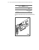
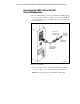
See Chapter 3 “Installation and Maintenance” of the RAID Array 3000
Controller Shelf Hardware User’s Guide for the SCSI bus and ID addresses of
the drives in the BA356 device expansion shelves. The target SCSI bus ID
assignments for a one, two, three, and four Device Expansion Shelves are also
shown.
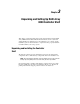
Connecting Cables
The cable connections to complete the controller shelf installation consist of:
■ Serial control cable connection between the controller shelf host I/O
module and the maintenance PC
■ SCSI cable connections between the controller shelf device I/O modules
and the SCSI connectors on the device expansion shelf personality I/O
Modules
■ AC power cord connections between the AC power source, the UPS,
and the controller and device expansion shelves
The cable connection information is covered in detail in Chapter 3
“Installation and Maintenance” of the RAID Array 3000 Controller Shelf
Hardware User’s Guide. This manual also contains specific cable installation
procedures for a controller shelf and up to four expansion shelves.
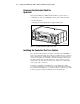
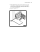
Charging the UPS Battery
CAUTION: To prevent possible damage to the equipment, the input voltage
level of the UPS must be set to your specific line voltage before proceeding.
Refer to the UPS manual and set the input level to your AC power sources.
See the AC power wiring diagram in the cabling section of Chapter 3
“Installation and Maintenance” of the RAID Array 3000 Controller Shelf
Hardware User’s Guide to connect the UPS to the power source and the
individual shelves in your RAID Array 3000 storage system installation. This
diagram shows the gray and black power cord connections, along with a
jumper connection that must be made between the UPS and the host I/O
module in the controller shelf.