SSL2000 Series Library Reference Guide First Edition (April 2000) Part Number 187193-001 Compaq Computer Corporation Compaq Confidential – Need to Know Required Writer: Bob Young Project: Compaq StorageWorks SSL2000 Series Library Reference Guide Comments: Part Number: 187193-001 File Name: a-frnt.
Notice © 2000 Compaq Computer Corporation. Compaq, the Compaq logo, and StorageWorks Registered in U. S. Patent and Trademark Office. All other product names mentioned herein may be trademarks or registered trademarks of their respective companies. Confidential computer software. Valid license from Compaq required for possession, use or copying. Consistent with FAR 12.211 and 12.212, Commercial Computer Software, Computer Software Documentation, and Technical Data for Commercial Items are licensed to the U.
Contents About This Guide Text Conventions........................................................................................................xi Symbols in Text.........................................................................................................xii Symbols on Equipment..............................................................................................xii Cabinet Stability ......................................................................................................
iv Compaq StorageWorks SSL2000 Series Library Reference Guide System Description continued Library Features ....................................................................................................... 1-7 Control Panel .................................................................................................... 1-9 Display.............................................................................................................. 1-9 Power Supply........................................
About This Guide Installation continued Configuration Options ........................................................................................... 2-23 SCSI Options .................................................................................................. 2-23 Library Options .............................................................................................. 2-25 Bar Code Options ...........................................................................................
vi Compaq StorageWorks SSL2000 Series Library Reference Guide Operation continued Using the Status Mode ........................................................................................... 4-12 Exiting the Status Mode.................................................................................. 4-12 Exploring the Status Mode ............................................................................. 4-12 Library Status Submenu..................................................................
About This Guide Chapter 6 Troubleshooting Introduction ............................................................................................................. 6-1 Platform Problems ................................................................................................... 6-1 General Drive Errors................................................................................................ 6-2 Error Recovery ...................................................................................
viii Compaq StorageWorks SSL2000 Series Library Reference Guide Figure 3-5. Unplugging the PTM motor housing assembly control cable .............. 3-7 Figure 3-6. Connecting a patch cable...................................................................... 3-9 Figure 3-7. Connecting to Library units................................................................ 3-10 Figure 3-8. Location stop pin................................................................................ 3-11 Figure 3-9.
About This Guide List of Tables Table 1-1 Library Models........................................................................................ 1-2 Table 1-2 Library Front View.................................................................................. 1-7 Table 1-3 Library Rear View................................................................................... 1-8 Table 1-4 Tape Cartridge Magazine ......................................................................
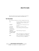
About This Guide This guide is designed to be used as step-by-step instructions for installation and as a reference for operation, maintenance, and troubleshooting. Text Conventions This document uses the following conventions to distinguish elements of text: Keys Keys appear in boldface. A plus sign (+) between two keys indicates that they should be pressed simultaneously. USER INPUT User input appears in a different typeface and in uppercase. FILENAMES File names appear in uppercase italics.
xii Compaq StorageWorks SSL2000 Series Library Reference Guide Symbols in Text These symbols may be found in the text of this guide. They have the following meanings. WARNING: Text set off in this manner indicates that failure to follow directions in the warning could result in bodily harm or loss of life. CAUTION: Text set off in this manner indicates that failure to follow directions could result in damage to equipment or loss of information.
About This Guide Any surface or area of the equipment marked with these symbols indicates the presence of a hot surface or hot component. If this surface is contacted, the potential for injury exists. WARNING: To reduce the risk of injury from a hot component, allow the surface to cool before touching. Power Supplies or Systems marked with these symbols indicate the equipment is supplied by multiple sources of power.
xiv Compaq StorageWorks SSL2000 Series Library Reference Guide Getting Help If you have a problem and have exhausted the information in this guide, you can get further information and other help in the following locations. Compaq Technical Support In North America, call the Compaq Technical Phone Support Center at 1-800-OK-COMPAQ. This service is available 24 hours a day, 7 days a week. For continuous quality improvement, calls may be recorded or monitored.
About This Guide Compaq Authorized Reseller For the name of your nearest Compaq authorized reseller: ■ In the United States, call 1-800-345-1518. ■ In Canada, call 1-800-263-5868. ■ Elsewhere, see the Compaq website for locations and telephone numbers. Compaq Confidential – Need to Know Required Writer: Bob Young Project: Compaq StorageWorks SSL2000 Series Library Reference Guide Comments: Part Number: 187193-001 File Name: a-frnt.
Chapter 1 System Description Introduction The Compaq StorageWorks SSL2000 Series is a tape library system that combines Advanced Intelligent Tape™ (AIT) drive technology with advanced robotics. Designed for high duty-cycle online and near-online applications, such as hierarchical storage management, it is a superior performer in high-volume backup and archival service.
1-2 Compaq StorageWorks SSL2000 Series Library Reference Guide Library Models Libraries are currently available with: ■ A tabletop or rackmount version ■ One or two tape drives ■ An optional Pass-Through Mechanism (PTM) for connecting up to five library units ■ AIT 2 technology ■ A Fast/Wide, Low Voltage Differential (LVD)/Single Ended (SE) SCSI-2 interface The drives used in the Library read from and write to 8 mm AIT 2 data tape cartridges with a native capacity of 35 GB or 50 GB (see Table 1-
System Description 1-3 The SmartScale Storage architecture gives you a truly scaleable library that can smoothly expand to meet your growing storage needs. You can start with a system configured to your present requirements, confident that as your storage needs evolve, adding units and extending the PTM can easily modify the Library. Add drives for faster performance or magazine space for greater capacity, as needed.
1-4 Compaq StorageWorks SSL2000 Series Library Reference Guide In a library system with many drives, it might be desirable to use multiple SCSI buses for the drives so the data transfer rate of the drives is not limited by bus bandwidth. Individual drives can be connected to separate hosts. Using special software, one of the hosts can act as a master server, processing all robotics commands and permitting several hosts to share a common database.
System Description 1-5 SCSI Configuration The Library standard SCSI interface is a Fast/Wide LVD/SE using high-density, 68-pin D-series connectors. For more information, see Chapter 2, “Installation.” SCSI Bus Performance Considerations Drives With a standard Fast/Wide SCSI interface, each drive offers a sustained native data transfer rate of 6 MB/s. In a two-drive unit, the total native rate is twice these rates.
1-6 Compaq StorageWorks SSL2000 Series Library Reference Guide Bus Length Limitations A single-ended Fast/Wide SCSI bus is limited in length to 10 ft (3 m), including cabling within the units. A differential Fast/Wide SCSI bus can be up to 82 ft (25 m) in length, including cabling within the units. If all devices and host adapter are LVD, length is limited to 39 ft (12 m).
System Description 1-7 Library Features Figures 1-1 through 1-3 shows some of the external features of the Library (see Tables 1-2 through 1-4). 1 2 3 cc0005 Figure 1-1. Library front view Table 1-2 Library Front View Figure Legend Description 1 Control panel 2 Magazine door 3 Power switch Compaq Confidential – Need to Know Required Writer: Bob Young Project: Compaq StorageWorks SSL2000 Series Library Reference Guide Comments: Part Number: 187193-001 File Name: b-ch1 System Description.
1-8 Compaq StorageWorks SSL2000 Series Library Reference Guide 1 5 2 2 3 3 4 4 5 1 6 6 cc0015 7 Figure 1-2.
System Description 1-9 Control Panel The control panel features a 4-line by 20-character backlit liquid crystal display, four LED indicators and four buttons. The buttons let you navigate through the menu structure to select and display operating modes, device status, diagnostic and maintenance functions, device history and error statistics, and library system configuration. The functions of the control panel are described in detail in Chapter 4, “Operation.
1-10 Compaq StorageWorks SSL2000 Series Library Reference Guide Tape Cartridge Magazine The rugged polymer magazine fits into an extruded track, which assures precise positioning for the library robotics (see Figure 1-3 and Table 1-4). 1 2 3 cc0003 Figure 1-3. Tape cartridge magazine Compaq Confidential – Need to Know Required Writer: Bob Young Project: Compaq StorageWorks SSL2000 Series Library Reference Guide Comments: Part Number: 187193-001 File Name: b-ch1 System Description.
System Description 1-11 Table 1-4 Tape Cartridge Magazine Figure Legend Description 1 Slot 18 2 Mail slot 3 Slot 0 The front slot in the magazine is a Mail Slot, used to add or remove cartridges without interrupting library operation.
1-12 Compaq StorageWorks SSL2000 Series Library Reference Guide Advanced Design Features Embedded Diagnostics The Library provides three levels of embedded diagnostics: Power-On Self Test (POST ) — Performs various verification tests on the system’s configuration, host interface and device control functions, as well as memory tests when you power on the unit. User Diagnostics — Lets you display and change configuration options. Selected from front panel.
System Description 1-13 Capacity The Library with its 20-cartridge magazine offers the formatted capacities listed in Table 1-5. NOTE: Capacities are based on 19 storage slots.
Chapter 2 Installation Introduction This chapter describes how to install the Compaq StorageWorks SSL2000 Series Library (AIT Library), including: ■ Unpacking ■ Releasing the lockdown mechanism ■ Setting up desktop and rackmount models ■ Setting up interfaces and cables ■ Configuring the Library ■ Configuring a Library system ■ Setting up reserved slots ■ Configuration options and settings Unpacking Unpack the Library and place it in the desired physical location.
2-2 Compaq StorageWorks SSL2000 Series Library Reference Guide Releasing the Lockdown Mechanism If you have not done so, release the lockdown mechanism on the Library using the lockdown screw at the back of the unit ( 1 Figure 2-1). 1 cc0014 Figure 2-1. Lockdown mechanism screw To release the lockdown mechanism: 1. Turn off the unit and then disconnect the power cord from the AC power source. 2. If necessary, reposition the unit for easier access to the back panel.
Installation 3. Turn the spring-loaded lockdown screw at the back of the unit counter-clockwise. The screw pops out and the lockdown mechanism releases from the shuttle ( 1 Figure 2-2). 4. Connect AC power and then turn the unit power on. 1 1 cc0016 Figure 2-2. Releasing the lockdown mechanism To lock the lockdown mechanism: 5. Park the shuttle assembly by selecting the Maintenance menu and then Park from the Main menu.
2-4 Compaq StorageWorks SSL2000 Series Library Reference Guide 9. Push in on the spring-loaded lockdown screw at the back of the unit and turn it clockwise ( 1 Figure 2-3). This secures the shuttle to a bracket and locks it in place. 1 cc0017 Figure 2-3. Locking the lockdown mechanism Setting up the Desktop Model The Library tabletop model requires no mechanical assembly for mounting. Place the unit on a desk, table, server top, or other stable, horizontal surface.
Installation Precaution If you do mount the Library in a storage cabinet, be sure to take the following precautions: CAUTION: Before moving and installing a Library into a storage cabinet, make sure that the robot is parked (using the control panel) and the lockdown mechanism is locked. CAUTION: To prevent tipping, never slide units out of the storage cabinet so that more than 57 lb (226 kg) or 20% of the total storage cabinet weight is extended at any time.
2-6 Compaq StorageWorks SSL2000 Series Library Reference Guide cc00018 Figure 2-4. Removing the desktop outside cover Installing the Rackmount Top Cover Install the rackmount top cover to protect the internal components of the Library prior to mounting it into a storage cabinet (see Figure 2-5). To install the rackmount top cover: 1. Place the top cover over the Library with each side flange facing to the outside of the unit. 2. Slide the top cover forward until it is flush with the front panel.
Installation 3. Secure the top cover to the Library using two screws (see Figure 2-5). 4. Remove the rubber feet. cc0019 Figure 2-5. Installing the rackmount top cover Compaq Confidential – Need to Know Required Writer: Bob Young Project: Compaq StorageWorks SSL2000 Series Library Reference Guide Comments: Part Number: 187193-001 File Name: c-ch2 Installation.
2-8 Compaq StorageWorks SSL2000 Series Library Reference Guide Installing the Inner Slide Members Attach an inner slide member to both sides of the Library using the following procedures. Make sure you attach each inner slide member of the rackmount slide assembly to the Library first and then each middle and outer slide members to the storage cabinet. To attach the inner slide members to the Library: NOTE: The left and right slides are the same so there is no risk of confusing the parts upon reassembly.
Installation Table 2-1 Rackmount Slide Parts Figure Legend Description 1 Inner slide member 2 Middle slide member 3 Outer slide member 2. Remove each inner member from each rackmount slide assembly. 3. Attach both inner members to the Library sides. Use six pan-head screws (three each side) inserted through the upper row of holes in each inner member (see Figure 2-7). cc0026 Figure 2-7.
2-10 Compaq StorageWorks SSL2000 Series Library Reference Guide Installing the Panel Extensions NOTE: The left and right slides are the same so there is no risk of confusing the parts upon reassembly. 1. Place a panel extension against one side of the Library so that the holes in the panel extension are aligned with the two holes in the chassis (see Figure 2-8). 2 1 cc0027 Figure 2-8. Installing the panel extension 2. Install two screws through the holes in the panel extension into the Library.
Installation Installing the Rackmount Model into a Storage Cabinet 1. With the inner slide members attached to the Library, install the middle and outer slide members to the storage cabinet, following the installation instructions in the Compaq Rack Planning Guide. 2. Using two people, lift the Library and visually align the inner and middle slide members. Carefully insert the Library’s inner slide members into the extended middle slide members. 3.
2-12 Compaq StorageWorks SSL2000 Series Library Reference Guide 2 3 2 1 3 1 4 5 5 4 6 6 7 7 8 99 10 11 12 : ; 15 13 cc0013 < 14 > = Figure 2-9.
Installation Table 2-2 Connectors, SCSI Terminator, and Cables Figure Legend Description 1 SCSI host cable 2 SCSI jumper cable 3 SCSI terminator 4 Expansion ports 5 DRV 0 + LIB 6 Diagnostic 7 Motor 8 DRV 1 9 AC power cord : SCSI terminator (1 drive configuration) ; SCSI host cable (1 drive configuration) < SCSI jumper cable (2 drive configuration) = SCSI host cable (2 drive configuration) > SCSI terminator (2 drive configuration) Power Cord Connector The power cord connector i
2-14 Compaq StorageWorks SSL2000 Series Library Reference Guide SCSI Interface Connectors The Library is equipped with a Low Voltage Differential/Single-Ended (LVD/SE) SCSI interface. NOTE: If your Library is used on a single-ended SCSI bus, the internal wiring length of any rackmounted SCSI system can approach the maximum length specification of a single-ended SCSI bus. You must locate the storage cabinet close to the host computer to avoid excessive bus length.
Installation ■ 34-pair twisted-pair ■ Each end of a twisted pair ground connected to chassis ground ■ Maximum cable length of 10 ft (3 m) for a single-ended Fast/Wide SCSI bus, including the internal wiring of SCSI device ■ Maximum cable length of 82 ft (25 m) for a differential Fast-Wide SCSI bus, including the internal wiring of SCSI device ■ Maximum cable length of 39 ft (12 m) for an LVD SCSI bus ■ Internal cable lengths of 22 in (56 cm) for Drive 0 and Robot and 15 in (38 cm) for Drive 1 ■
2-16 Compaq StorageWorks SSL2000 Series Library Reference Guide Setting a SCSI ID 1. Turn the Library on and wait until the Power-On Self Test (POST) terminates and the Primary or Secondary Default screen appears on the display. You can toggle between the two with the π and θ buttons. Loader Idle Drv 0: No Tape Drv 1: Unloaded Or Ready 0 ____ ___ 9 10 ____ ___ 18 2. At the Default screen, press the Enter button. The screen displays the following Main menu.
Installation 4. To select a configuration option, press the π or θ button on the control panel until the υ appears next to the option you want to change. The first two choices on this menu, SCSI Options and Library Options, are actually categories of options. In this case, choose SCSI Options. Press the Enter button to display the options for that category.
2-18 Compaq StorageWorks SSL2000 Series Library Reference Guide Configuring a Library System All Libraries are factory-shipped as stand-alone units. To include them in a multi-unit Library system, you must first configure one unit as the master and all other units as slaves. Any Library can be configured to be a stand-alone, master, or slave.
Installation 4. Press Enter to move the cursor to the second line. 5. Use the θ and π buttons to change the option to Master. 6. Press Enter to save the selection. NOTE: The change will not take effect until you reboot. The Slave Unit You can configure the slave unit on the work bench before installation or after it is installed in a storage cabinet.
2-20 Compaq StorageWorks SSL2000 Series Library Reference Guide 3. Press the θ button to move the υ to Library Options, then press the Enter button. The following screen appears: υ Configuration *Standalone Unload Mode *Implicit ⁄ 4. Press Enter to move the cursor to the second line. 5. Use the θ and π buttons to change the option to Slave. 6. Press Enter to save the selection. The display at lines 3 and 4 changes to let you specify a numerical ID for the slave module.
Installation How Reserved Slots are Numbered Ordinary cartridge slots are numbered from the front of the magazine to the rear ( 4 Figure 2-10). If you reserve one slot, it becomes Reserved Slot #1 in the last slot of the magazine ( 1 Figure 2-10). If you reserve two slots, slot #17 becomes Reserved Slot # 1 ( 3 Figure 2-10), while slot #18 becomes Reserved Slot #2 ( 2 Figure 2-10). Additional reserved slots continue in this rear-to-front pattern.
2-22 Compaq StorageWorks SSL2000 Series Library Reference Guide To Reserve Slots 1. From the Default screen, press the Enter button to display the Main menu. 2. From the Main menu, scroll down to the Configure menu and press the Enter button to display the following Configure submenu: υ SCSI Options: Library Options Date and Time Set Element Base ⁄ 3. Scroll down to Library Options and press the Enter button. 4. Scroll down to Reserved Slots and press the Enter button.
Installation Configuration Options The following options are available in the Configuration menu. SCSI Options Library Parity: Lets you enable or disable the library robotics SCSI bus parity checking. The default is Library Parity Enabled. Library Bus ID: Lets you set the SCSI addresses of the library robotics. The default is 0. Drive 0 Bus ID: Lets you set the SCSI addresses of the drives.
2-24 Compaq StorageWorks SSL2000 Series Library Reference Guide Initialize Element Status: Lets you specify the unit’s response to the SCSI INITIALIZE ELEMENT STATUS command. The possible settings are No Inventory, Force Inventory, and Force Label Scan. The default is No Inventory. Unit Attn Report: Lets you select reporting of All or only One unit attention conditions.
Installation Library Options Configuration: Lets you configure the Library as a stand alone, master, or slave unit. The default is stand alone. NOTE: For multi-unit operation, you must first install a Pass-Through Mechanism. See chapter 3 “Installing and Removing the Pass-Through Mechanism” for further instructions. Unload Mode: Lets you determine whether a SCSI MOVE MEDIUM command is interpreted as Implicit or Explicit.
2-26 Compaq StorageWorks SSL2000 Series Library Reference Guide Baud Rate: Lets you set the data transmission rate of the trace port. This function is intended for use by CEs only. The default is 38400 bits/s. Reserved Slots: Lets you withdraw from use a specified number of slots in the back of the magazine. Some host software imposes size limits on tape library magazines for licensing purposes, and does not operate with a library that exceeds the licensed size. The default is 0.
Installation Set Element Base Transport: Lets you set the base address of the robotics mechanism. The default is 0000. Storage: Lets you set the base address of the 19 magazine slots. The default is 0001. Transfer: Lets you set the base address of the drive. The default is 00E0 for Drive 0. Import/Export: Lets you set the base address of the mail slot. The default is 00D0. Set Serial Number Serial Number: Lets you alter the unit’s serial number as stored in the unit.
2-28 Compaq StorageWorks SSL2000 Series Library Reference Guide Configuration Settings Table 2-3 lists the configuration settings for the Library.
Installation Table 2-3 Library Configuration Options continued Option Settings Default Tape Alert Mode Logging Disabled, No Exceptions, Unit Attention, Rec Error (cnd), Rec Error (unc), No Sense, On Request Logging Disabled Library Options Configuration Stand Alone, Master, Slave Stand Alone Unload Mode Implicit, Explicit Implicit Element Base One Based, Zero Based Zero Based Auto Clean Enabled, Disabled Disabled Library Mode Random, Sequential 0, Sequential 1, Sequential Split Random
2-30 Compaq StorageWorks SSL2000 Series Library Reference Guide Table 2-3 Library Configuration Options continued Option Settings Default Set Element Base Options Transport NNNN (hex) 0x0000 Storage NNNN (hex) 0x0001 Transfer NNNN (hex) 0x00F0 Import/Export NNNN (hex) 0x00E0 Set Serial Number Options Serial Number Format To Match nnnnnnnnnnnn Format To Match nnnnnnnnnnnn Set Default Options Compaq Defaults Compaq Defaults Compaq defaults NOTE: The options listed in this table represen
Chapter 3 Installing and Removing the Pass-Through Mechanism Introduction This chapter describes how to install and remove the Pass-Through Mechanism (PTM). The PTM enables the transfer of a single tape cartridge between two or more SSL2000 Series Libraries. The PTM can be used to connect up to five Libraries increasing the storage capacity of the entire library system.
3-2 Compaq StorageWorks SSL2000 Series Library Reference Guide Installing a Pre-Assembled PTM To install a pre-assembled PTM: 1. Access the rear panels of the Library units in the storage cabinet and disconnect each one from its AC power source. 2. Loosen the screws that secure the Library unit’s mounting ears to the front of the storage cabinet. Loosen the screws just enough to allow the Library units to move slightly in and out.
Installing and Removing the Pass-Through Mechanism 6. Holding the PTM upright, position it against the rear panels so that the PTM motor housing assembly 1 slides into the available space and the two pilot pins 3 on the extrusion mate with the holes 2 in the rear of the top Library unit (see Figure 3-2). 1 2 3 3 cc0029 Figure 3-2.
3-4 Compaq StorageWorks SSL2000 Series Library Reference Guide 7. Attach the PTM to the master (top) unit using two bullet-nose thumbscrews 1 and washers through the top two holes in the extrusion (see Figure 3-3). Do not fully tighten the thumbscrews at this time. 1 cc0030 Figure 3-3. Securing the PTM to the master unit 8. Align the two holes on the extrusion with mounting holes on the slave unit and attach the PTM in place using two bullet-nose thumbscrews and washers ( 1 Figure 3-4).
Installing and Removing the Pass-Through Mechanism 1 cc0031 Figure 3-4. Securing the PTM to the slave unit NOTE: If a screw hole is offset, push the slave unit slightly forward to make a gap between it and the channel. This lets you start threading the thumbscrews into the slave unit. 9. Repeat Steps 7 through 9 for each additional slave unit. Do not fully tighten the thumbscrews at this time. 10. Tighten all rear storage cabinet slide screws. 11. Tighten all PTM thumbscrews. 12.
3-6 Compaq StorageWorks SSL2000 Series Library Reference Guide Removing a PTM To remove a PTM: 1. Access the rear panels of the Library units in the storage cabinet and disconnect each one from its AC power source. 2. Unplug the motor control cable from its connector on the PTM motor housing assembly (see Figure 3-5). 3. If the master unit (top) is to be removed for service, disconnect the motor cable and plug it into the unit directly below it (slave 0).
Installing and Removing the Pass-Through Mechanism cc0032 Figure 3-5. Unplugging the PTM motor housing assembly control cable 5. Remove the bullet-nose thumbscrews and washers (two per unit) that secure the PTM to the Library units (see Figure 3-4). 6. Gently pull the PTM out and away from the Library units.
3-8 Compaq StorageWorks SSL2000 Series Library Reference Guide Cabling the PTM and Multi-Unit Library System Cabling the PTM and multi-unit Library system includes attaching cables to the following interface connectors: ■ PTM motor housing assembly ■ Library unit Connecting to the PTM Motor Housing Assembly CAUTION: Make sure the power is off to the unit that you plug the motor connector into. 1. Connect one end of the control cable to the connector in the PTM motor housing assembly (see Figure 3-5).
Installing and Removing the Pass-Through Mechanism Connecting to Library Units 1. Attach a patch cable to one expansion port on the master unit ( 1 Figure 3-6). 1 cc0050 Figure 3-6. Connecting a patch cable Compaq Confidential – Need to Know Required Writer: Bob Young Project: Compaq StorageWorks SSL2000 Series Library Reference Guide Comments: Part Number: 187193-001 File Name: d-ch3 Installing and Removing the Pass-Through Mechanism.
3-10 Compaq StorageWorks SSL2000 Series Library Reference Guide 2. Use additional patch cables to connect successive slave units to the master unit. Connect all Library units in a daisy-chain fashion ( 1 Figure 3-7). 1 cc0051 Figure 3-7. Connecting to Library units Compaq Confidential – Need to Know Required Writer: Bob Young Project: Compaq StorageWorks SSL2000 Series Library Reference Guide Comments: Part Number: 187193-001 File Name: d-ch3 Installing and Removing the Pass-Through Mechanism.
Installing and Removing the Pass-Through Mechanism 3-11 Adding a PTM Extrusion This section describes how to add an extrusion to extend the PTM. To add an extrusion, you must first remove the PTM, the elevator car, and the bottom pulley assembly. To add an expansion module: 1. Remove the PTM (if already installed). 2. Remove the elevator car (described later in this section). 3. Remove the bottom pulley assembly (described later in this section). 4.
3-12 Compaq StorageWorks SSL2000 Series Library Reference Guide 5. Attach the tie bars with the screws to the PTM extrusion, making sure that the beveled edges of the tie bars are oriented as shown in (1 Figure 3-9). 1 cc0034 Figure 3-9. Attaching tie bars Compaq Confidential – Need to Know Required Writer: Bob Young Project: Compaq StorageWorks SSL2000 Series Library Reference Guide Comments: Part Number: 187193-001 File Name: d-ch3 Installing and Removing the Pass-Through Mechanism.
Installing and Removing the Pass-Through Mechanism 3-13 6. Insert the tie bars (now mounted on the main PTM extrusion 1) into the extension 2, aligning the two PTM extrusions so that the channel patterns match (see Figure 3-10). 1 2 cc0035 Figure 3-10.
3-14 Compaq StorageWorks SSL2000 Series Library Reference Guide 7. Attach the tie bars to the PTM extrusions using four screws (two each side). See Figure 3-11. 8. Move location stop pin to lowest PTM extrusion (1 Figure 3-8). cc0036 Figure 3-11.
Installing and Removing the Pass-Through Mechanism 3-15 Installing a New Belt 1. Obtain a belt from extension kit and then cut it to the appropriate length (see Figure 3-12). NOTE: A new full-length belt is marked 2, 3, 4, and so forth indicating where to cut per number of Library units the PTM will service. cc0037 Figure 3-12. Cutting the belt NOTE: The belt included with your kit accommodates up to four PTM extrusions.
3-16 Compaq StorageWorks SSL2000 Series Library Reference Guide 2. Thread the belt through the bottom pulley. Note the orientation of the belt teeth and the location stop pin ( 1 Figure 3-13). 3. Thread the belt through the top pulley. 1 cc0038 Figure 3-13.
Installing and Removing the Pass-Through Mechanism 3-17 4. Attach the belt clamp bracket to the belt on the side closest to the PTM motor housing assembly. Make sure one tooth of the belt fits tight in the space in the bracket ( 1 Figure 3-14). 1 cc0039 Figure 3-14.
3-18 Compaq StorageWorks SSL2000 Series Library Reference Guide 5. Replace the bottom pulley end cap, securing it with self-tapping screws on both sides ( 1 Figure 3-15). 1 cc0040 Figure 3-15. Replacing the bottom pulley end cap Compaq Confidential – Need to Know Required Writer: Bob Young Project: Compaq StorageWorks SSL2000 Series Library Reference Guide Comments: Part Number: 187193-001 File Name: d-ch3 Installing and Removing the Pass-Through Mechanism.
Installing and Removing the Pass-Through Mechanism 3-19 6. Slide the spring over the tension post and then snap into place so that it rests squarely against the inside of the PTM track ( 1 Figure 3-16). 1 cc0041 Figure 3-16. Snapping the spring over the tension post Compaq Confidential – Need to Know Required Writer: Bob Young Project: Compaq StorageWorks SSL2000 Series Library Reference Guide Comments: Part Number: 187193-001 File Name: d-ch3 Installing and Removing the Pass-Through Mechanism.
3-20 Compaq StorageWorks SSL2000 Series Library Reference Guide Removing the Elevator Car 1. Lay the PTM on a flat surface with the elevator car facing you (see Figure 3-17 and Table 3-1). 3 4 5 2 6 1 7 cc0042 Figure 3-17.
Installing and Removing the Pass-Through Mechanism 3-21 Table 3-1 PTM Components Figure Legend Description 1 Tensioner ramp 2 Elevator car 3 Upper pulley 4 PTM motor housing assembly 5 Captive screws (attaches elevator car to belt clamp) 6 Drive belt 7 Lower pulley 2. Remove the two screws that secure the elevator car to the belt clamp bracket ( 1 Figure 3-18). 1 cc0043 Figure 3-18.
3-22 Compaq StorageWorks SSL2000 Series Library Reference Guide 3. Press against the elevator springs to disengage the wheels from the PTM extrusion channel (see Figure 3-19). 4. Tilt the elevator to disengage the other pair of wheels. cc0044 Figure 3-19.
Installing and Removing the Pass-Through Mechanism 3-23 5. Lift the elevator car out of the PTM extrusion. cc0045 Figure 3-20. Removing the elevator car Compaq Confidential – Need to Know Required Writer: Bob Young Project: Compaq StorageWorks SSL2000 Series Library Reference Guide Comments: Part Number: 187193-001 File Name: d-ch3 Installing and Removing the Pass-Through Mechanism.
3-24 Compaq StorageWorks SSL2000 Series Library Reference Guide Replacing the Elevator Car 1. Position the belt clamp midway along the PTM. Place the elevator car into the PTM extrusion, over the belt clamp, engaging both pairs of wheels into the PTM extrusion channel. The wheels of the elevator car should ride in the "V" grooves of the PTM extrusion channel. The cartridge opening on the elevator car should face away from the PTM motor housing assembly (see Figure 3-19). 2.
Installing and Removing the Pass-Through Mechanism 3-25 2. Insert a paper clip in the hole so that it removes tension from the belt and then leave it in place while completing the procedure (see Figure 3-22). cc0047 Figure 3-22. Removing tension from the belt 3. Loosen the retaining screws to remove the two belt clamp plates (see Figure 3-15). 4. Remove the belt from the PTM.
3-26 Compaq StorageWorks SSL2000 Series Library Reference Guide 5. Remove the screws on both sides of the bottom pulley assembly ( 1 Figure 3-23). 1 cc0048 Figure 3-23. Releasing the bottom pulley assembly 6. Slide the bottom pulley assembly 1 out of the PTM extrusion 2 (see Figure 3-24). 1 2 cc0049 Figure 3-24.
Chapter 4 Operation Introduction This chapter describes operating the SSL2000 Series Library (AIT Library) through the control panel at the front of the unit.
4-2 Compaq StorageWorks SSL2000 Series Library Reference Guide Front Panel The front panel of the Library includes a power switch for the unit and the control panel, which has buttons, a display, and indicators (see Figure 4-1 and Table 4-1). 1 2 3 cc0005 Figure 4-1. Library front panel Compaq Confidential – Need to Know Required Writer: Bob Young Project: Compaq StorageWorks SSL2000 Series Library Reference Guide Comments: Part Number: 187193-001 File Name: e-ch4 Operation.
Operation Table 4-1 Library Front View Figure Legend Description 1 Control panel 2 Magazine door 3 Power switch Power Switch The power switch controls the supply of AC power to the Library front panel. It is a push-on, push-off switch. When the power is on, the backplane of the control panel display lights. Compaq Confidential – Need to Know Required Writer: Bob Young Project: Compaq StorageWorks SSL2000 Series Library Reference Guide Comments: Part Number: 187193-001 File Name: e-ch4 Operation.
4-4 Compaq StorageWorks SSL2000 Series Library Reference Guide Indicators and Buttons The control panel consists of four LED indicators, a four-line by 20-character backlit LCD display, and four buttons (see Figure 4-2 and Table 4-2). 2 3 2 1 4 4 3 5 9 6 7 8 cc0006 Figure 4-2.
Operation Table 4-2 Library Control Panel Figure Legend Description 1 Ready LED 2 User cleaner LED 3 Drive fault LED 4 Loader fault LED 5 Display panel 6 Escape button 7 Enter button 8 Scroll up button 9 Scroll down button LED Indicators There are four LED indicators on the control panel, labeled Ready (green), Use Cleaner (yellow), Drive Fault (red), and Loader Fault (red). The Ready LED (green) lights when the Library is ready to accept commands from the host computer.
4-6 Compaq StorageWorks SSL2000 Series Library Reference Guide Buttons There are four buttons on the control panel: Escape, Enter, π, and θ. The buttons do not directly control specific functions or options. Instead, you use the buttons to navigate from the Default screen through a multi-level menu structure, then select the desired option from the appropriate menu using the Enter button. Table 4-3 lists the effect of each of the four buttons under various conditions.
Operation Using the Escape Button to Access Status Mode To enter the Status Mode, which displays all aspects of the Library’s operating and configuration status, press the Escape button at the Default screen. The Library remains online.
4-8 Compaq StorageWorks SSL2000 Series Library Reference Guide Front Panel and Media Locks A security feature is available to avoid accidental interruption of Library operation by entering the Menu mode or removing cartridges while the host is accessing the Library. The front panel and the media can be electronically locked. When the front panel is locked, you can only enter the Menu mode after entering a 4-digit code.
Operation Initialization Screens After the POST completes, the library robotics are initialized. A series of screens similar to the one shown is displayed during this process. Compaq SSL2020TL Firmware Level 0X.XX Initializing Loader Default Screen After the POST diagnostics have concluded successfully and initialization is complete, the following Default screen appears. Note that the Default screen consists of two pages.
4-10 Compaq StorageWorks SSL2000 Series Library Reference Guide Fault Screen When a fault is detected, a screen similar to the one shown appears. In addition, either the Drive Fault or the Loader Fault LED on the control panel lights. Fault Code: 3004 Elevator Jammed Power Down to Clear The first line shows a numerical FSC. The second line shows a brief description of the error. The third and fourth lines contain a one- or two-line message describing the initial ERP.
Operation Power-Up Displays Default Display Escape Button Fault Display Enter Button Panel Lock Status Mode Main Menu Access Mail Slot Library Status Load/Unload Model Number Firmware Revision SCSI Bus ID SCSI Bus Parity Boot Version Flash Type Library Type Library Mode Library Config Vendor ID Product ID Baud Rate Transport Addr Storage Addr Transfer Addr Import/Export Serial Number Negotiation Mode Transfer Rate Unload Mode Auto Clean Mode Reserved Slots Mode Page 1F Length TUR Reporting Init Elem
4-12 Compaq StorageWorks SSL2000 Series Library Reference Guide Using the Status Mode You can enter the Status Mode by pressing the Escape button whenever the Default screen appears. Entering the Status Mode does not affect operation of the Library. When you enter the Status Mode, the following appears: υ Access Mail Slot Library Status Drive 0 Status Map Info ⁄ Exiting the Status Mode To exit the Status Mode, press the Escape button until the Status menu appears.
Operation Scroll through this screen to view the list of available options: ■ Model Number ■ Negotiation Mode ■ Firmware Revision ■ Transfer Rate ■ SCSI Bus ID ■ Unload Mode ■ SCSI Bus Parity ■ Auto Clean Mode ■ Boot Version ■ Reserved Slots ■ Flash Type ■ Mode Page 1F Length ■ Library Mode ■ TUR Reporting ■ Library Config ■ Initialize Element Status ■ Vendor Iden ■ Barcode Reader ■ Product Iden ■ Label Size ■ Baud Rate ■ Label Alignment ■ Transport Address ■
4-14 Compaq StorageWorks SSL2000 Series Library Reference Guide Scroll through this screen to view the list of available options: ■ Tape Motion ■ SCSI Bus ID ■ Firmware Revision ■ Cartridge Present ■ Hardware Error ■ Cleaning Needed ■ Write Protected Map Information Screen When you select Map Info, the following screen appears. The location being reported appears on Line 1. The content of the bar code on the label, up to 6 characters, appears on Line 4.
Operation Using the Menu Mode NOTE: When the Library enters the Menu mode, the Ready LED goes out. This means that the module is offline, and responds to all commands from the host with a SCSI Not Ready until you exit the Menu Mode and the Ready LED comes on. To prevent interruption of host operations, you can lock out the Menu Mode using the Security menu. See “Security Menu” later in this chapter. When all control panels are locked, you must enter your unlock code to display the Main menu.
4-16 Compaq StorageWorks SSL2000 Series Library Reference Guide Exiting the Menu Mode To exit the Menu Mode and return to the Default screen, press the Escape button repeatedly. Each time you press the Escape button, the display moves to a higher menu level. When the Main menu appears, pressing the Escape button once returns to the Default screen. At this point, the Ready LED lights.
Operation Maintenance Menu The Maintenance menu options, intended for operator use, are described in Chapter 5, “Maintenance.” Additional Maintenance menu options used by service technicians are described in the Compaq StorageWorks SSL2000 Series Library Maintenance and Service Guide. Configure Menu The Configure menu, how to use it, and the options available under it are described in Chapter 2, “Installation.” Security Menu Use the Security menu to lock the control panel.
4-18 Compaq StorageWorks SSL2000 Series Library Reference Guide An underline cursor displays under the first digit. To set the first digit, press the π button or the θ button until the number you want appears. To move the cursor to the second digit, press the Enter button. Repeat the process for each of the four digits. Be sure to remember the 4-digit number; you use it to enter the Menu Mode. Use an unlock code of 0000 to disable control panel locking.
Operation Displaying Firmware Revisions You can display the library robotics firmware revision at any time by pressing the Escape button at the Default screen to enter the Status Mode. It displays as one of the options on the Library Status submenu of the Status menu. It is also displayed on line 2 of the POST Screen and the Initialization Screens.
4-20 Compaq StorageWorks SSL2000 Series Library Reference Guide 3. The * at the left of line 2 (the current selection) disappears, meaning you have not selected an item from the list. NOTE: The contents of the lists on line 2 and line 4 vary as follows. Initial Screen – From Line The list on line 2 (the From line) includes every drive and magazine slot (including mail slots) with cartridges. (You cannot retrieve a cartridge from an empty slot or drive.
Operation Press the Enter button to select Drive 1 as the destination. The following Confirmation Screen appears: From: Slot 11 To: Drv 0 ENTER to Execute ESCAPE to Cancel Press the Enter button to execute the load or unload or the Escape button to cancel or return to the From entry screen. When you press the Enter button, the following screen appears: If the source is a drive, the word Unload appears in place of the word Load on line 4.
4-22 Compaq StorageWorks SSL2000 Series Library Reference Guide 1 1 Re ad y Us Cleae ne r Dr Faive ult Lo ad Fa er ult Es ca pe En ter cc0010 Figure 4-4. Magazine in place Removing the Magazine Whenever a magazine is installed inside the module it is locked in place to prevent tampering or accidental removal. To remove the magazine, enter the Menu Mode by pressing the Enter button at the Default screen. At the Main menu, select Remove Magazine, and press the Enter button.
Operation Inserting Cartridges into the Magazine A full magazine is shown in Figure 4-5. Insert cartridges so that the label end with the write protect switch is outward, with the write protect switch toward the bottom of the magazine. The lowest numbered cartridge slot in the magazine is closest to the handle ( 2 Figure 4-5). The highest numbered cartridge slot is the farthest from the handle ( 1 Figure 4-5). 1 1 2 2 cc0008 Figure 4-5.
4-24 Compaq StorageWorks SSL2000 Series Library Reference Guide Using the Mail Slot The mail slot is used only with host software that supports this feature ( 1 Figure 4-6). To access the mail slot from the Default screen, press the Escape button to enter the Status Mode. Press the Enter button and the magazine door opens, exposing the Mail Slot. The magazine remains locked inside the module. The mail slot of the magazine can be tilted forward to insert or remove a cartridge.
Operation Write Protecting Cartridges To write protect a tape cartridge (disable data recording), slide the write protect switch up so that no orange color is visible in the lower small window (see Figure 4-7). To enable data recording, slide the write protect switch down until the orange indicator shows in both small windows. SAFE REC cc0011 Figure 4-7.
4-26 Compaq StorageWorks SSL2000 Series Library Reference Guide Bar Code Labels Bar code labels should meet the following specifications (see Figure 4-8): ■ Size: 2.1 in x 0.4 in (55 mm 1 x 10.2 mm 2) ■ Stock: Label stock with adhesive back and matte overlaminate ■ Location: Mounts next to write-protect switch on cartridge ■ Text: Six characters, any combination of alphabetic and numeric ■ Bar Code: Code 39, Codabar, 3-of-9, standard 2-of-5, or interleaved 2-of-5, with a length of eight digits.
Operation Multi-Unit Library System Operation Powering Up All Library units should be powered up at the same time through the storage cabinet supplied power, or the master unit (top) should be powered up last if the Library units are powered up individually. Connecting a Multi-Unit Library System The following procedure explains how to set the SCSI ID and SCSI host connections: 1. For maximum performance, connect only 2 AIT-2 drives to each SCSI host adapter. 2.
Chapter 5 Maintenance Introduction This chapter describes the Clean Drive and Demo options contained in the Maintenance menu. You use the Clean Drive option to clean tape drives installed in the SSL2000 Series Library (AIT Library). You can use the Demo option to fully exercise the Library robotics. CAUTION: Only qualified service technicians should perform the remaining options contained in the Maintenance menu.
5-2 Compaq StorageWorks SSL2000 Series Library Reference Guide Running a Cleaning Cartridge There are two ways to run a cleaning cartridge: ■ Automatically—by enabling the Auto Clean option ■ Manually—by selecting the CLEAN DRIVE command from the Maintenance submenu on the front panel display Running a Cleaning Cartridge Automatically You can configure the Library so that it runs the cleaning cartridge automatically.
Maintenance 3. Scroll down to the Maintenance menu and press the Enter button. The following Maintenance submenu appears: υ Clean Drive Diagnostic menu Demo Menu Flash Update ⁄ 4. Press the Enter button once to select Clean Drive. The following Cleaning submenu appears: Cleaning: υ *Drv 0 Using: *Slot 0 5. Press the Enter button to accept Drive0. The υ moves to line 4 of the display. The choices available on Line 4 are slots 0 through 18. Press the Enter button again to use the cartridge in Slot 0.
5-4 Compaq StorageWorks SSL2000 Series Library Reference Guide Removing the Cleaning Cartridge 1. Examine the Default screen on the control panel to make sure the cleaning cartridge has been unloaded from the drive. If not, then unload it using the Load/Unload menu, as described in Chapter 4, “Operation.” 2. Remove the magazine from the Library. See “Inserting and Removing Cartridges” in Chapter 4. 3. Remove the cleaning cartridge from the magazine. 4.
Chapter 6 Troubleshooting Introduction This chapter describes the problems that can cause the SSL2000 Series Library (AIT Library) to malfunction, including: ■ Platform problems ■ General drive errors ■ Error recovery ■ Fault Symptom Codes (FSCs) Platform Problems Incorrect installation and configuration cause platform problems. In this case, the Library appears to be operating normally, but no data can be interchanged. You may or may not get an error code on the control panel.
6-2 Compaq StorageWorks SSL2000 Series Library Reference Guide General Drive Errors General drive errors usually result from a miscommunication between a module’s processor and a drive processor or a mechanical malfunction within the Library. Both platform problems and general drive errors display an error message and a Fault System Code (FSC) on the control panel. Use the FSC to report errors to your Technical Support representative, or in some cases, to determine a recovery procedure.
Troubleshooting TROUBLESHOOTING AND ERROR RECOVERY ERROR, FAULT, MALFUNCTION Determine Suspected Error Type PLATFORM No FSC displayed. Normal front panel operation GENERAL DRIVE FSC and ERP displayed on control panel Cycle the power to the library Follow the ERP on the control panel Retry Find FSC in Table 6-2 Check configuration in Ch.
6-4 Compaq StorageWorks SSL2000 Series Library Reference Guide Error Recovery Procedures Table 6-1 lists ERPs for errors reported on the front panel of the Library. This list includes only those procedures that can be safely performed by you. The Compaq StorageWorks SSL2000 Series Library Maintenance and Service Guide includes additional procedures that can be performed by a qualified service technician.
Troubleshooting Fault Symptom Codes (FSCs) FSCs that appear on the Fault screen described in Chapter 4, “Operation.” A descriptive message and instructions for clearing the fault accompany each FSC. If a fault persists, look up the FSC in Table 6-2 to determine the error recovery procedure or to report to your Technical Support representative.
Appendix A Specifications Introduction This appendix lists the following specifications and regulatory requirements met by the Compaq StorageWorks SSL2000 Series Library (AIT Library): ■ ■ Specifications: ! Operational performance ! Reliability ! Power ! Mechanical ! Environmental ! Acoustic emission Regulatory requirements: ! Safety ! Electromagnetic Emission (EM) ! FCC and VCCI Compaq Confidential – Need to Know Required Writer: Bob Young Project: Compaq StorageWorks SSL2000 Series
A-2 Compaq StorageWorks SSL2000 Series Library Reference Guide Table A-1 Operational Performance Specifications Description Specification Host Interface Fast Wide SCSI (differential) Low Voltage Differential (LVD) Number of cartridges, full magazine 19 Media type AIT 8 mm, Advanced Metal Evaporated Number of drives 1 or 2 Load time 15 sec (max), including picking from slot Unload time 15 sec (max), including returning to slot Rewind speed 160 in/sec Sustained native data transfer rate, max
Specifications Table A-2 Reliability Specifications (Drives) Description Specification Data error rate (recoverable) 1 in 10 bytes MTBF 250,000 hr @ 30% duty cycle MTTR 30 min Head life 50,000 tape motion hrs 17 Table A-3 Reliability Specifications (Library System Robotics) Description Specification Life expectancy, load/unload operations 1,000,000 cycles Design life 7 yrs Table A-4 Power Specifications Description Specification Voltage 115 to 240 VAC Current 1.5 to 1.
A-4 Compaq StorageWorks SSL2000 Series Library Reference Guide Table A-5 Mechanical Specifications (Tabletop Model) Description Specification Height 7.9 in (20 cm) Width 17.3 in (44 cm) Depth: Overall Behind panel 24 in (61 cm) 22.75 in (57.79 cm) Weight: Single drive Dual drive 41 lbs (18.6 kg) 41.5 lbs (18.8 kg) Table A-6 Mechanical Specifications (Rackmount Model) Description Specification Height 6.7 in (17 cm) Width 17.3 in (44 cm) Depth: Overall Behind panel 24 in (61 cm) 22.
Specifications Table A-7 Environmental Specifications (Operating) Description Specification Dry bulb temperature 50°F to 104°F (10°C to 40°C) Temperature gradient 1.8°F/min (1°C/min) Temperature shock 59°F (15°C) over 2 min Wet bulb temperature 78.
A-6 Compaq StorageWorks SSL2000 Series Library Reference Guide Table A-9 Environmental Specifications (Storage/Transit) Description Specification Dry bulb temperature -40°F to 140°F (-40°C to 60°C) Temperature gradient 45°F (25°C)/hr (across the range) Temperature shock 27°F (15°C) (over 2 min) Wet bulb temperature 86°F (30°C) Relative humidity (non-condensing) 5% to 95% Humidity gradient 10%/hr Altitude (sea level) -100 ft to +10,000 ft (-305 m to 3050 m) Table A-10 Acoustic Emission Leve
Specifications Safety The Library carries the following Regulatory Agency product safety certifications. Table A-11 Regulator Agency Product Safety Certifications Description Specification Certification Standard UL Listed UL 1950 TUV/Product Service EN 60 950 GS Mark CE Mark EMC Directive, Low Voltage Directive Canadian UL Listed CSA 22.2 No. 950 Electromagnetic Emission (EM) Notice This equipment has been tested using double shielded cables for EM compliance.
A-8 Compaq StorageWorks SSL2000 Series Library Reference Guide FCC Notice This equipment has been tested and found to comply with the limits for a Class A digital device, pursuant to Part 15 of the FCC rules. These limits are designed to provide reasonable protection against harmful interference when the equipment is operated in a commercial environment.
Specifications FCC and VCCI Requirements The following FCC and VCCI notices apply to the Library. Statement for Equipment Meeting FCC Class A Requirements This equipment has been tested and found to comply with the limits for a Class A digital device, pursuant to Part 15 of the FCC rules. Operation is subject to the following two conditions: (1) This device may not cause harmful interference and (2) This device must accept any interference that may cause undesirable operation.
A-10 Compaq StorageWorks SSL2000 Series Library Reference Guide Equipment Meeting VDE Class B Requirements (VFG 1046/84 and VFG 243/91 for Germany) Für Bundesrepublik Deutschland For Federal Republic of Germany Pour la République féderal d’Allemagne Bescheinigung des Herstellers/Importeurs Dieses Gerät ist Übereinstimmung mit den Bestimmungen der BMPT Vfg. 243/1991 und Vfg. 46/1992 in Verbindung mit EN55022:1987 (DIN VDE 0878-3:11.89) oder Vfg. 1046/1984 mit Vfg. 483/1986, funkentstört.
Specifications VCCI Notice for Japan Class I Equipment Japanese Voluntary Control Council for Interference (VCCI). This equipment is in the 1st Class category (information equipment to be used in commercial and/or industrial areas) and conforms to the standards set by the Voluntary Control Council for Interference by Information Technology Equipment aimed at preventing radio interference in commercial and/or industrial areas.
Index Acoustic Noise Declaration A-8 Advanced Design Features library 1-12 Advanced Intelligent Tape (AIT) drive technology 1-1 AIT Library attaching cables to 3-10 Auto Clean Option 2-25 Automatically Cleaning Cartridges 5-2 Bar Code Reader described 1-11 Baud Rate Option 2-26 Belt cutting to size for PTM extrusions 3-16 Buffer Size drives 1-12 Bus Length Limitations SCSI 1-6 Button Functions control panel 4-7 Buttons θ (scroll down) 4-6 υ (scroll one line) 4-16 π (scroll up) 4-6 enter 4-6 escape 4-6 unl
2 Compaq StorageWorks SSL2000 Series Library Reference Guide cleaning 5-2 Cartridges See Tape cartridges CE Diagnostics described 1-12 Certifications regulator agency product safety A-7 Check Digit Option 2-26 Cleaning cartridges 5-2 Cleaning Cartridge removing 5-4 Cleaning Cartridges automatically 5-2 manually 5-2 Cleaning Confirmation Screen 5-3 Cleaning in Progress Screen 5-3 Cleaning Submenu 5-3 Combination Lock electronic 1-11 Commands CLEAN DRIVE 5-2 LOAD/UNLOAD 4-21 SCSI ALLOW/PREVENT MEDIUM REMOVA
Index D E Data compression 1-12 Data Compression Rates 1-5 Data Transfer Rates dependencies 1-5 Default Options configuring 2-27 Default Screen 2-16, 4-9 Demo Submenu 5-4 Design Features advanced 1-12 Desktop Model outside cover removal 2-5 setting up 2-4 Diagnostics CE 1-12 described 1-12 power-on self test 1-12 user 1-12 Display Screen control panel 1-9 described 1-9 Displaying Firmware revision 4-19 Drive 0 Bus ID Option 2-23 Drive 1 Bus ID Option 2-23 Drive address set 2-27 Drive Fault LED 4-5 Drive
4 Compaq StorageWorks SSL2000 Series Library Reference Guide Front View components 1-7, 4-2 G General Drive Errors 6-2 H Handling Tape Cartridges 4-24 help additional sources xiv Compaq authorized resellers, telephone numbers xiv Compaq website xiv technical support telephone numbers xiv http://www.compaq.
Index Limitations SCSI bus length 1-6 Load/Unload Menu described 4-19 initial screen (from line) 4-20 initial screen (to line) 4-20 scroll list (to line) 4-20 Loader Fault LED 4-5 Loading/Unloading tape cartridges 4-19 Lockdown Mechanism 1-6 locking 2-3 releasing 2-2 screw location 2-2 Lockdown Mechanism Screw (locking) illustrated 2-4 Lockdown Mechanism Screw (releasing) illustrated 2-3 Locking lockdown mechanism 2-3 Locking the Front Panel 4-8 M Magazine emergency removal of 4-22 inserting 4-23 removing
6 Compaq StorageWorks SSL2000 Series Library Reference Guide N Negotiation Mode Option 2-23 Number of Drives Supported 1-2 Numbering reserved slots 2-21 Numbering Display Option 2-25 O Operation library 4-1 Option PTM 3-1 Options configuration 2-23 Precautions rackmount installation 2-5 Product ID Option 2-23 PTM installing a pre-assembled 3-2 removing 3-7 PTM Extrusion adding 3-12 installing a new belt 3-16 PTM Installation illustrated 3-4 PTM motor housing assembly attaching cable to 3-9 PTM Port Cove
Index Removing the Magazine 4-21 described 4-22 Removing/Inserting Cartridges magazine removal 4-21 Required Cables 2-11 Requirements SCSI cables 2-14 tape cartridges 4-24 Reserved Slots configure submenu 2-22 described 2-20 how numbered 2-21 Reserved Slots Option 2-26 RJ-45 receptacle xii Robotics 1-11 exercising using Demo submenu 5-4 set address of 2-27 S Safety certifications A-7 Screens cleaning confirmation 5-3 cleaning in progress 5-3 configure menu 2-16 configure submenu 2-22 default 2-16, 4-9 fau
8 Compaq StorageWorks SSL2000 Series Library Reference Guide Setting Up Interfaces one or two drive setup 2-11 Setting up the Desktop Model 2-4 Setting up the Rackmount Model 2-4 Slave Unit configuring 2-19 Slide Installation rackmount 2-8 Slots how to reserve 2-22 reserved 2-20 Specifications acoustic emission level A-6 bar code labels 4-26 cable 2-14 environmental (operating) A-5 environmental (packed or unpacked) A-5 environmental (storage/transit) A-6 mechanical (rackmount) A-4 mechanical (tabletop) A
Index U Unit Attn Report Option 2-24 Unload Mode Option 2-25 Unloading/Loading tape cartridges 4-19 Unlock Code 4-18 Unlock/Open Button 4-2 Unpacking described 2-1 locking lockdown mechanism 2-3 releasing lockdown mechanism 2-2 Use Cleaner LED 4-5 User Diagnostics described 1-12 Using Menus 4-10 Using the Mail Slot 4-24 V VCCI Notice for Japan Class I Equipment A-11 Vendor ID Option 2-23 Versions rackmount 1-2 tabletop 1-2 W warnings electrical shock xiii rack stability xiii Write Protect Switch illustra