installation guide hp StorageWorks virtual arrays va 7000 family Edition January 2003 Part number A6183-96143 Printed in U.S.A.
Notice Trademark Information © Hewlett-Packard Company, 2000-2003. All rights reserved. Red Hat is a registered trademark of Red Hat Co. Hewlett-Packard Company makes no warranty of any kind with regard to this material, including, but not limited to, the implied warranties of merchantability and fitness for a particular purpose.
Revision History September 2001 Change Page Added Quick Connect Guides to list of documents available during installation. 7 Clarified the valid range for loop ID is 0 -125 26 Added HP-UX 11.20 to the supported operating systems for Command View SDM 35 Changed disk enclosure numbering from 1-6 to 0-5. 31 Added information on identifying what array settings to change 24 January 2002 Change Page Added additional non-native supported operating systems.
July 2002 Change Page Added note on connecting only CVSDM hosts to the array until LUN security is enabled. 27 Added VA 7410 back-end Fibre Channel cabling 29 Removed Compaq Tru64 and Compaq OpenVMS from supported non-native operating systems. 35 Added note on using the CVSDM GUI to create the host port behavior table. Also added maximum number of table entries. 45 Add Step 22 to connect all hosts to the array after LUNs have been created and LUN security implemented.
contents 1 Virtual Array Installation Guide 7 Other Information You Will Need 7 Operating Environment 8 Virtual Array Configurations 8 Virtual Array Enclosures 8 Hardware Installation 15 Step 1. Unpack the array 15 Step 2. Rack the array 15 Step 3. Set FC Loop Speed Switch (VA 7400 with DS 2405 Disk System) 16 Step 4. Connect the power cords 19 Step 5. Connect the RS-232 terminal 20 Step 6. Power-on the array controller enclosure 22 Configuring the Array Operating Settings 24 Step 7.
Minimum System Requirements for Windows 40 arrays Installation Steps 40 Installing Command View SDM on Linux Red Hat 42 Minimum System Requirements for Linux Red Hat 42 Installation Steps 43 Final Array Configuration 44 Step 18. Gather Host WWNs 44 Step 19. Build the Host Port Behavior Table 45 Step 20. Create LUNs 46 Step 21. Build the Secure Manager LUN Security Table 47 Step 22.
Virtual Array Installation Guide This guide provides instructions on installing the hardware and software components for the HP StorageWorks Virtual Array products. When the steps in this guide are completed, the virtual array will be fully operational and ready for use.
Operating Environment It is essential that HP StorageWorks Virtual Array products be installed in an environment that provides the proper operating conditions. Refer to the HP StorageWorks Virtual Array User & Service Guide for a complete list of electrical and environmental specifications. Make sure the environment meets these specifications before installing and operating the array. Virtual Array Configurations Enclosure Nameplate Type of Enclosure No. of Enclosures in VA 7100 No.
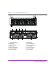
Figure 1 4 VA 7100 Controller Enclosure (A/AZ) 2 3 1 6 5 7 14 8 9 10 13 1 - Power/Standby Switch 2 - System LEDs 3 - Disk Drive Slot No.
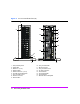
Figure 2 VA 7100 Controller Enclosure (D) 1 14 2 7 8 13 9 10 11 15 12 16 5 4 3 6 1 - Power/Standby Switch 2 - System LEDs 3 - Disk Drive 1 (of 15) 4 - Disk Drive LEDs 5 - Disk Drive Slot No.
Figure 3 VA 7110 Controller Enclosure 2 3 4 1 6 5 7 10 12 11 A6218A 9 A6218A 8 disk 2 14 host 2 disk 13 15 1 - Power/Standby Switch 2 - System LEDs 3 - Disk Drive Slot No. 1 (of 15) 4 - Disk Drive 1 (of 15) - M/D1* 5 - Disk Drive LEDs 6 - ESD Ground Receptacle 7 - Array Controller 1 - M/C1* 8 - DISK FC Connector and LED - M/C1.G1* host 16 9 - HOST FC Connector - M/C1.
Figure 4 VA 7400 Controller Enclosure (A/AZ) 2 3 4 1 6 5 7 8 9 10 11 16 12 15 1 - Power/Standby Switch 2 - System LEDs 3 - Disk Drive Slot No.
Figure 5 VA 7410 Controller Enclosure (A/AZ) 2 3 4 1 6 5 7 9 10 11 8 16 12 15 1 - Power/Standby Switch 2 - System LEDs 3 - Disk Drive Slot No.
Figure 6 VA 7110/7400/7410 Disk Enclosure (A/AZ) 4 3 6 5 7 8 16 2 9 10 11 17 12 13 15 14 18 1 - Power/Standby Switch 2 - System LEDs 3 - Disk Drive Slot No.
Hardware Installation Step 1. Unpack the array 1 Follow the unpacking instructions printed on the shipping container to unpack the controller enclosure. 2 Follow the unpacking instructions printed on the shipping container to unpack any disk enclosures (VA 7110/7400/7410 only). Step 2. Rack the array WARNING To prevent the rack from tipping over, install the enclosures to maintain the center of gravity as low as possible. A full enclosure may weigh up to 104 pounds (47 kg).
Step 3. Set FC Loop Speed Switch (VA 7400 with DS 2405 Disk System) When installing a VA 7400 that includes DS 2405 Disk Systems, the FC Loop Speed switch on the disk enclosure LCCs must be set to 1GB/s. Failure to set the switch on both LCCs in each disk enclosure will disrupt the FC loop and cause the entire array to malfunction. This step is not required when installing a VA 7410 or VA 7110. These products have a 2 Gbit/sec back-end, which is the default FC Loop Speed switch setting on the DS 2405.
Figure 7 LCC Removal and Installation B C D A A LCC B cam latch C locking thumbscrew D LCC slot Virtual Array Installation Guide 17
Figure 8 Setting FC Loop Speed Switch Set the FC Loop Speed to 1GB/s 18 Virtual Array Installation Guide
Step 4. Connect the power cords WARNING To avoid electrical fire hazard, use a branch circuit breaker properly rated for each power supply. If multiple enclosures are connected to a single branch circuit, multiply the number of enclosures times the maximum current, then select a circuit breaker with at least a 20% higher current rating. See Table 2. To optimize system availability, each power supply should be connected to a separate power bus. All wiring should meet or exceed local electrical wiring codes.
Figure 9 Connecting Enclosure Power Cords Caution If it becomes necessary to completely remove power from the array, you must unplug both power cords from both ac power connectors on the array rear panel. Step 5. Connect the RS-232 terminal 1 Connect one end of the null-modem serial cable to the RS-232 port on either array controller. See Figure 10. Note The RS-232 port on either array controller can communicate with both controllers.
4 Start a terminal emulator using HyperTerminal or Reflections.
Step 6. Power-on the array controller enclosure a Push in the power/standby switch to the “ON” position. See Figure 11. Immediately after the array is powered on, each component in the array enclosure performs a power-on self-test. b Verify the power-on self-test passed: all LEDs should be solid green. During power-on self-test, the an initialization sequence is displayed followed by the Ready prompt.
Disk Sector Reformatting If the disks in the array controller enclosure are formatted with 512-byte sectors, they are reformatted to 520-byte sectors at this time. Sector reformatting takes 30 to 60 minutes to complete, depending on disk drive capacity. Larger capacity disks take longer to reformat. If the disks have 520byte sectors, this process is not performed. The disk activity LEDs will flash during sector reformatting.
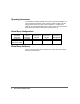
Configuring the Array Operating Settings There are several settings that control the operation of the array. The values selected for these settings are determined by the operating environment. The various settings and when they need to be changed are listed in the following table. Identify the settings that need to be changed and perform the required steps.
Step 7. Change the controller default host port behavior Note It is recommended that the default controller port behavior be set for the operating system of the host running CommandView SDM. This ensures that the management station will still function if the host port behavior table in the array is corrupted or lost.
Step 9. Change the controller port topology 1 To change the port topology for controller 1 enter the following command, selecting 2 for Public Loop or 4 for Direct Fabric Attach: mgr -t < 2 | 4 > -c 1 2 When prompted to reset, enter no. 3 To change the port topology for controller 2 enter the following command, using the same topology value used for controller 1: mgr -t < 2 | 4 > -c 2 4 When prompted to reset, enter no if additional settings must be changed.
Step 12. Format the array controller enclosure Formatting the array controller enclosure performs the following operations: — — — — — Places identifying drive stamps on each drive in the array. Reserves image disks in the controller enclosure. Deletes all LUNs. Initializes the memory maps. Creates pseudo-LUN 0 allocated with zero bytes so the host will recognize the array. ■ To format the array, enter the following command: vfpfmt Step 13.
Front-end fiber optic connections depend on the type of connectors used by the controller and the type of host adapter or type of connector in the hub or switch. — The VA 7100 controller uses GBICs with SC (large form factor) connectors. It only supports host adapters with SC connectors, and uses cables with SC-SC connectors. — The VA 7110/7400/7410 controller uses integrated LC (small form factor) connectors.
VA 7410 The VA 7410 has two independent back-end Fibre Channel loops to improve performance. The cabling configuration should balance the distribution of disk modules across both loops. Here are some things to remember when connecting the VA 7410 back-end cabling: — All disks in the controller enclosure are connected to loop 1. — The first disk enclosure should be connected to loop 2 to balance the disks.
4 Set the address switches on the disk enclosures. See Figure 14. Each disk enclosure should have a unique address. Both link controller cards in the enclosure must be set to the same address. For ease of management, it is recommended that odd addresses (1, 3, 5) be used for disk enclosures on loop 1 and even addresses (0, 2, 4) be used for disk enclosures on loop 2. Because the two back-end FC loops are independent, disk enclosures on different loops can have the same address.
Figure 13 VA 7400 Back-End Fiber Optic Cabling & Addressing (6 Disk Enclosures) Virtual Array Installation Guide 31
Figure 14 VA 7410 Back-End Fiber Optic Cabling & Addressing (6 Disk Enclosures) FC Loop 1 32 Virtual Array Installation Guide FC Loop 2
Figure 15 Fiber Optic Cables & Configurations To Host Adapter Connector A3583A 2m SC-SC M/M FO Cable A3531A 16m SC-SC M/M FO Cable A3735A 50m SC-SC M/M FO Cable A3736A 100m SC-SC M/M FO Cable To VA 7100 HOST FC Connector Or To C7534A To Host Adapter Connector Or To VA 7400/7410 DISK FC Connector C7524A 2m LC-LC M/M FO Cable C7525A 16m LC-LC M/M FO Cable C7526A 50m LC-LC M/M FO Cable C7527A 100m LC-LC M/M FO Cable To VA 7400/7410 HOST FC Connector Or To Disk Enclosure PORT 0/1 FC-AL Connector C7534A F
Step 16. Power-on all array enclosures 1 Power-on the disk enclosures. 2 Power-on the controller enclosure. Disk Sector Reformatting If the disks in the disk enclosures are formatted with 512-byte sectors, they are reformatted to 520-byte sectors at this time. Sector reformatting takes 30 to 60 minutes to complete, depending on disk drive capacity. Larger capacity disks take longer to reformat. If the disks have 520-byte sectors, this process is not performed.
Installing CommandView SDM Software ■ If you are adding an array to a new system that will require the installation of the CommandView SDM software, continue with "Install CommandView SDM software" ■ If you are adding an array to an existing system that is currently being managed using CommandView SDM, you must add the new array to the management configuration. Perform the following steps to do this.
Installation Tips ■ For the latest updates on CommandView SDM installation procedures, refer to the README file provided on the HP CommandView SDM CD-ROM. ■ Before installing CommandView SDM, make sure the latest operating system patches and the latest host adapter drivers and patches are installed on the host. ■ Have a copy of the HP StorageWorks CommandView SDM Installation and User Guide available for reference.
Installing Command View SDM on HP-UX Minimum System Requirements for HP-UX Host ■ HP-UX 11.0/11.
array is automatically added to the EMS configuration and array events will be detected and reported. Installation Steps 1 Log onto the system as root or superuser. 2 Insert the CommandView SDM software CD into the CD-ROM drive. 3 Identify the device file for the CD-ROM: ioscan -fnCdisk 4 Create a mount point directory. For example: mkdir /cdrom Use a directory that does not exist 5 Mount the CD device file using the device file and directory from the preceding steps.
9 Once the software installation is complete, log out, then log back in to reset the path. This completes the installation of the CommandView SDM software. See the HP StorageWorks CommandView SDM Installation and User Guide for information on configuring and using the management software.
Installing Command View SDM on Windows Minimum System Requirements for Windows ■ Administrator privileges (Required) Host ■ Windows NT 4.
Once the installation is complete, an icon for the CommandView SDM Launcher is placed on the desktop. Installing the SAM HostAgent on OpenView SAM When installing the CommandView SDM software in a SAM environment, the SAM Host Agent must be installed on hosts connected to the arrays that will be managed. The SAM Host Agent must be installed and running on a host to allow the SAM management client to detect and manage the array . 1 Launch the SAM GUI.
Installing Command View SDM on Linux Red Hat Minimum System Requirements for Linux Red Hat ■ Red Hat Linux 7.1 with kernel 2.4.
Installation Steps 1 Log on as root or superuser. 2 Create a directory for the software. For example: mkdir /tmp/cmdview 3 Insert the CommandView SDM software CD into the CD-ROM drive. 4 If necessary mount the CD device file. For example: mount /dev/cdrom /mnt/cdrom 5 Copy the contents of the CD (or download from the web) into the directory created in step 3.
Final Array Configuration Step 18. Gather Host WWNs The host WWN is used for defining the port behavior for a host, and for managing LUN security. Either the node or port WWN can be used. Before building either the host port behavior table or the LUN security table, you must gather the WWNs associated with each host that will be accessing the array. This step is only required in heterogeneous host environments, or if Secure Manager will be used to implement LUN security.
■ For other supported operating systems use the utilities included with their respective host adapter. The Quick Connect Guide downloaded from the internal SPOCK web site should include information on how to locate and use the operating system or host adapter utilities. ■ Most FC switches provide a method for displaying the WWN of the device connected to each switch port. Step 19.
Table 3 Host Port Behavior Strings Operating System HP-UX Windows NT Windows 2000 Linux Solaris AIX NetWare OpenVMS Tru64 MPE/iX VA 7100 (Firmware HP 01 and HP02) hpuxfcdriver windows/linuxfcdriver windows/linuxfcdriver windows/linuxfcdriver Not Supported Not Supported Not Supported Not Supported Not Supported Not Supported VA 7100 or VA 7400 (Firmware HP11 and greater) Hpux WinNT Win2000 Linux Solaris AIX NetWare OpenVMS Tru64 MPE (VA 7100 only) VA 7410 or VA 7110 Hpux WinNT Win2000 Linux Solaris AIX
Valid LUN number ranges are listed in the following table. Product (Firmware Rev) VA 7100 (HP01 and HP02) VA 7100 ( HP11 and greater) VA 7110/7400/7410 LUN Number Range 0-63 0-127 0-1023 A Word About LUN 0 It is recommended that you always create LUN 0. When LUN 0 is created, it is automatically assigned a LUN security permission of configure-write for all hosts. This ensures that regardless of which host you install the CommandView SDM software on, it will be able to manage the array.
Solving Installation Problems The following section identifies common installation problems and solutions. If the problem is not included here, contact support for assistance. Hardware Problems PROBLEM VFP Status Not "Ready" SOLUTION If the array status displayed in the VFP is not "Ready", perform the following steps: 1 Reset the array: vfpmgr -R full When the reset is complete, check the array status. If it still not Ready, continue with the next step.
PROBLEM When installing a VA 7400, none of the disk enclosures are visible and one or more of the following errors occur: Data Unavailable Hot Spare Unavailable Capacity Depletion Catastrophic Redundancy Loss Missing Drive No Map Disks SOLUTION This is typically caused by failing to set all the FC Loop Speed switches on the DS 2405 LCCs to 1GB/s. Make sure the switch on every LCC is set to 1GB/s.
front panel, see the hp surestore virtual arrays installation guide. When security has been disabled, continue with the steps below. 1 Read the LUN security table from the array into a file: armsecure –r –f -p } 2 Identify which LUNs the non-functioning host can access. You will need to know the World Wide Node name of the host to identify its entries in the table. 3 On one of the entries which grants the host access to a LUN, modify the permissions to include configure (C).
2 Add the IP address for each client requiring access to the arrays connected to the host. Or remove the IP address for any clients you no longer want to have access. Single client IP addresses can be added, or a range of IP addresses can be added using the wild card “*”. For example; 10.62.128.* grants access to any client on subnet 128. The use of wildcards is recommended when connecting from clients configured for dynamic host configuration protocol (DHCP). 3 Save the configuration file.
6 Check the Launcher to ensure the array is now displayed. You can also execute the armdsp -i command to display the arrays that were discovered. If this does not solve the problem, contact support for assistance.