P9000 XP Storage Replication Manager Software for VMware vCenter SRM version 2.0 Administrative Guide Abstract This guide contains detailed instructions for installing, removing, configuring, and using the P9000 Virtualization Adapter. The intended audience has independent knowledge of related OS software and of HP disk arrays and software.
© Copyright 2009, 2013 Hewlett-Packard Development Company, L.P. Confidential computer software. Valid license from HP required for possession, use or copying. Consistent with FAR 12.211 and 12.212, Commercial Computer Software, Computer Software Documentation, and Technical Data for Commercial Items are licensed to the U.S. Government under vendor's standard commercial license. The information contained herein is subject to change without notice.
Contents 1 VMware Site Recovery Manager overview.....................................................5 Applicable Products..................................................................................................................5 Prerequisites.............................................................................................................................5 RMSRA20 configurations...........................................................................................................
HP disk arrays do not appear in Site Recovery Manager.........................................................44 RMSRA20 does not install...................................................................................................44 Virtual machines do not start at the recovery site after failover.................................................44 Virtual machines do not start at the recovery site during testFailover..........................................44 Error Messages on SRM log files..........
1 VMware Site Recovery Manager overview The VMware Site Recovery Manager (SRM) protects the virtual machine systems on Vmware from disasters and other emergencies. It streamlines the protection of critical virtual machines with data, and continuously tests their availability for the highest level of business continuity. The Virualization Adapter requires two sites: a protected site (for production) and a recovery site (for backup and testing).
Table 1 RMSRA20 services • Service name Display name Startup type EventLog Event Log Automatic vpxd VMware VirtualCenter Server Automatic vmware-dr VMware Site Recovery Manager Service Automatic RMXP SRA and Array “Supported version of RMXP SRA and RAID Manager and microcode” (page 6) shows the support matrix of the RMXP SRA (rmsra command) and RAID Manager delivered with Micro code of the Array.
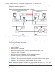
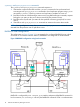
Primary and secondary conceptual configurations for RMSRA20 Figure 1 (page 7) is a conceptual diagram that shows the SRM configuration used by the RAID Manager for implementing SRA2.0. Figure 1 Primary and seconday configurations for SRA 2.0 Coordination process of SRM and SRA 2.0 Discovery of Arrays and Devices During SRM configuration, RM SRA is called to discover available arrays and replicated devices.
1. 2. 3. SRM makes a request to RM SRA to find available arrays. RM SRA connects to a RAID Manager Instance and requests all groups to find array controller information (WWN) and, using RAID Manager commands, to find remote arrays. RM SRA returns the results to SRM. Discovery Devices sequence The Device discovery sequence is: 1. SRM makes a request to RM SRA to find replicated devices on both the local (protected) and Remote (recovery) arrays. 2.
1. 2. 3. 4. 5. SRM makes a request to RM SRA to failover to replicated devices on a remote (recovery) array. RM SRA connects to a RAID Manager instance and requests finding replicated CA_SVOL on the recovery array using RAID Manager commands. RM SRA looks and checks for CA SVOLs that are members of data replication groups and then executes horctakeover -SS to make R/W SVOLs.
syncOnce and querySyncstatus commands The syncOnce and querySyncStatus command sequence is: 1. SRM makes a request to RM SRA with the syncOnce command to be synchronized and executes periodic querySyncStatus commands to check replication progress using syncID returned by syncOnce. Checking continues until replication completes or times out. 2. RM SRA connects to a RAID Manager instance and, using RAID Manager commands, requests finding the sync status on the source device returned by the protection arrays.
mode, User and Password for the array must be entered on the Add Array Manager GUI (see “Configuring SRM and P9000 (XP) disk array” (page 28)). RAID Manager local configuration using VCD Both VC and RMSRA20 are configured on Windows 2003. RAID Manager is configured via RDM on either Linux, solaris/x86, Windows, or VM. Figure 3 (page 11) shows a local configuration using Virual Command Device (VCD). For more information on VCD, see the P9000 Raid Manager User Guide.
Figure 4 RMSRA20 remote configuration using Telnet RM SRA is configured by SRA command.pl as an interface adapter and RMSRA20 commands. In remote connections, since SRA command.pl calls RMSRA20 commands on a remote RAID Manager, RMSRA20 is included with the HP P9000 Raid Manager installation. See the RAID Manager User Guide for supported systems. NOTE: Executing RMSRA20 over Telnet does not work if the RAID Manager instance in running on Windows, because Windows does not have a Telnet server.
Figure 5 RMSRA20 configuration using RAID Manager on VM RM SRA is configured by SRA command.pl as an interface adapter and uses the RMSRA20 command. In case of a remote storage connection configuration, SRA command.pl calls the RMSRA20 command on a Guest OS running a RAID Manager instance. The Guest OS can then use either the Linux or Solaris/x86 operating systems.
Figure 6 RAID Manager configuration for RMSRA20 Fiber Address conversion table The VMware ESX Server uses WWN and LUN# notation for device discovery. The fiber conversion table number for HORCM should be changed by using the $HORCMFCTBL variable. For example: • C:\HORCM\etc> set HORCMFCTBL=3 • C:\HORCM\etc> horcmstart This variable is set automatically to HORCMFCTBL=3 by the RMSRA20 command. If you specify the [-auto] option, you must also specify the LUN number in horcm.
Figure 7 RAID Manager configuration files example 1 For the instance number and target port in the example in Figure 8 (page 16): • X is the RAID Manager instance number • BC is not used for testFailover • CL4-G-1 is the target port for the ESX Server RMSRA20 configurations 15
Figure 8 RAID Manager configuration files example 2 NOTE: The conditions that testFailover (executed on CA/CAJ_SVOL) are: • BC licence is not installed (does not register as Group for BC ). • SRM or the $SplitReplication variable specifies = true. Or: • BC licence is installed. • SRM or the $SplitReplication variable specifies = true. • $RMSRATMU variable should be specified MU#, which does not exis as group for BC on horcm*.conf .
This testFailover configuration is required the conditions below. - To be able to communicate between HORCM of primary site and HORCM of recovery site. - In NON stopping test of APP, CA Sync CTG/CAJ volumes must be used. Snapshot volume for testFailover The snapshot volume for testFailover must be created as a volume using Point-in-time-Split, and must be set as a write disable volume after testFailover is completed.
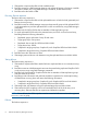
Usually, RAID Manager commands and HORCM must have the same privileges. If HORCM is executed with Local System privileges, RAID Manager commands will not attach to HORCM, because the RAID Manager command will be denied permission to communicate with HORCM through the Mailslot. If the HORCM instance is running with Local System privileges, RAID Manager commands do not attach to the HORCM instance because permission will be denied.
Table 3 Failover Action and Configurations (continued) SRM component Component name Failover actions Failover testfailover Split = false Split = true +BC (at time split Unused. See ) Note 2 Available Available +CoW (at time Unused. See split ) See Note 3 Note 2 Available Available +BC/CoW (without at time split ) Available Available Unused. See Note 2 Legend: Fail means that RMSRA20 returns with error. Unused means that RMSRA20 does not use it Note 1.
Figure 10 Remote configuration The testFailover configuration requires the following: • Ability to communicate between HORCM of the primary site and recovery sites. • CA Sync CTG/CAJ volumes must be used in a NON stopping test of APP. RMSRA20 does not use BC_SVOLs with the failover for the following reasons: • If BC_SVOL is used with CAJ(Async), data is due to ASYNC data transfer. DB may be started with old data even though BC_SVOL has data consistency.
Making standalone device/consistency groups SRM (AM) manages to do failover using the datastore standalone device. The consistency group for the datastore is generated automatically during the device information reported by RMSRA20. In Figure 11 (page 21) at the protection site, the consistency group is configured using datastore “LU01_LDEV19”, “LU02_LDEV20”, and “LU03_LDEV21”. The standalone device is configured using datastore “LU13_LDEV31”, “LU16_LDEV34”, and so on.
Figure 13 Device Pair list SRM (AM) shows the relation between the Device_Name of the horcm.conf and the datastore name.
2 Installation procedure The HP9000 SRA Software provides the files shown in “RMSRA20 files” (page 23). Table 4 RMSRA20 files No. Title File name Installation files 001 RMSRA20 RMXPSRA.exe DIR\command.pl DIR\rmsra20.exe DIR\rmsra20.linux DIR\rmsra20.solaris DIR\rmsra20.xsolaris DIR\rmsra20.hp DIR\rmsra20.aix NOTE: DIR is \storage\sra\RMXP. The is shown by HKEY_LOCAL_MACHINE\SOFTWARE\VMware, Inc.
C:\>net STOP vmware-dr The VMware Site Recovery Manager Service service is stopping. The VMware Site Recovery Manager Service service was stopped successfully. C:\>net START vmware-dr The VMware Site Recovery Manager Service service is starting. The VMware Site Recovery Manager Service service was started successfully. 4. For a remote configuration using Telnet, copy/Ftp the rmsra20 command as follows: • For a remote connection on Linux, FTP from DIR\rmsra20.linux to /HORCM/usr/ bin/rmsra20 on Linux.
Defining system variables using the GUI 1. 2. Open System Properties on the Control Panel. Select the Advanced tab, click the Environment Variables button, and add HORCMROOT, RMSRATOV, and RMSRATMU to System Variables (see Figure 15 (page 25)). Figure 15 Environment Variables dialog box 3. Reboot Windows.
Figure 16 VMware display example To update the software version: 1. Download new rmhtcsra.exe file from the VMware web site, and save it in a temporary folder. 2. Delete the installed RM SRA with Addition and deletion of application on the control panel. 3. Execute rmhtcsra.exe. 4. Restart the VMware Site Recovery Manager Service by entering one of the following commands if vmware-dr will be started. C:\>net STOP vmware-dr The VMware Site Recovery Manager Service service is stopping.
Figure 17 Verifying the version Uninstallation procedure 1. 2. Deletes the installed RM SRA with Addition and deletion of application on the control panel. Restart VMware Site Recovery Manager Service by entering the following command if vmware-dr will be started. C:\>net STOP vmware-dr The VMware Site Recovery Manager Service service is stopping. The VMware Site Recovery Manager Service service was stopped successfully. C:\>net START vmware-dr The VMware Site Recovery Manager Service service is starting.
3 Configuring SRM and P9000 (XP) disk array This chapter summarizes the steps to set up SRM and the HP disk array for use with RM SRA. The following procedures assumes that LUNs for the ESX Server are already assigned on the production site and recovery site, and the assigned LUNs for the ESX Server are known as HP disk array Ports, Port WWN, LUN number.
Configuring SRM (AM) to communicate with RMSRA20 Adding Array Manager 1. Configure the Array Manager on protection. When the protected and recovery SRM servers have been paired, click add an Array Manager to configure the Array Manager to use RMSRA20 (see Figure 18 (page 29)). Figure 18 Configure Array Manager 2. Add RMSRA20 to the protection side Array Manager.
Figure 19 Add Array Manager 3. 30 For an RMSRA20 configuration using remote connection, enter HORCM instance and IP Address to connect to the RAID Manager instance via RMSRA20, specifying the following formats (see Figure 20 (page 31)).
Figure 20 HORCM remote connection instance Configuring SRM (AM) to communicate with RMSRA20 31
• To connect to the RAID Manager on a remote UNIX Host, enter one of the following: ◦ HORCMINST=X@Host-name, which connects to HORCMINST=X on the Remote UNIX Host. ◦ $HORCMINST@Host-name, which connects the $HORCMINST setting to the Remote Login Environment on a UNIX Host. NOTE: If the array is set as the authentication mode, the remote user must have completed the authentication for its array. If no root user is needed for the use of Telnet, you must have permission to use the RAID Manager commands.
Figure 21 HORCM local connection instance • 5. To connect to the RAID Manager on the current Windows system, enter one of the following: ◦ HORCMINST=X, which connects to HORCMINST=X on the current Windows host. ◦ $HORCMINST, which connects to %HORCMINST% set to the current Windows host. Enter the username and password as dummy. NOTE: If the array is set as the authentication mode command device, enter the username and password (sraadmin) for the array user. 6.
Figure 22 Protected site array manager adapter information 7. 34 To configure the Array Manager on recovery, when the protected and recovery SRM servers have been paired, click add an Array Manager to configure Array Manager to use RMSRA20.
Figure 23 Configuring Array Manager on recovery Configuring SRM (AM) to communicate with RMSRA20 35
8. To add RMSRA20 to the recovery side Array Manager, define an appropriate name as Display Name and Select RAID Manager Storage Replication Adapter from an SRA Type that is connected to RMSRA20.
Figure 25 Configure the virtualization adapter with a remote Telnet connection ◦ To connect to the RAID Manager on a remote UNIX host enter one of the following commands: – HORCMINST=X@Host-name, which connects to HORCMINST=X on the remote UNIX host. – $HORCMINST@Host-name, which connects the $HORCMINST setting to the Remote Login Environment on the remote UNIX host. NOTE: If the array is set as the authentication mode, the remote user must have completed the authentication for its array.
• For an RMSRA20 configuration using local connection, enter the HORCM instance to connect to the RAID Manager instance via RMSRA20, specifying the following formats: Figure 26 Configure the virtualization adapter for local configuration ◦ Enter HORCMINST=X to connect to HORCMINST=X on the Windows Host. Enter Username & password as dummy. NOTE: If the array is set as the authentication mode command device, Enter Username & password (sraadmin) for the array user.
Figure 27 Array Manager summary screen Verifying Array Manager on protection Verify that the Local Array ID and Remote Array ID are discovered by the protection array manager (see Figure 28 (page 40)).
Figure 28 Array Pairs tab Enabling devices and verifying datastores Verify that the local and remote devices have been discovered by the protection array manger: 40 • The local device name and remote device name are the dev_name on horcm*.conf. • The direction is rightness. • The datastore is mapped to the correct PVOL. Figure 29 (page 41) shows a sample of the Protected Devices screen.
Figure 29 Protected devices screen Verifying the devices and replicated datastore on recovery Verify that the local and remote devices have been discovered with the following information by the recovery array manger: • The local device name and remote device name are the dev_name on horcm*.conf. • The direction is rightness. • The datastore is mapped to the correct PVOL. Figure 30 (page 42) shows a sample of the Recovery Devices screen.
Figure 30 Recovery Devices screen Create protection groups You are ready to create protection groups in the protected site using SRM. Protection groups (containing virtual machines) fail over together to the recovery site during test and recovery. For more information on creating protection groups, see the VMware Site Recovery Manager Administration Guide. Create recovery plans Create recovery plans on the recovery site.
4 Executing failover and failback with SRM This section discusses failover and failback with SRM and provides a scenario as a guide for the manual failback process. Failover Failover occurs when an SRM recovery plan is executed, and the SRM recovery plan is configured to fail over SRM protection groups that use replicated PVOLs and SVOLs on HP disk arrays as a datastore. During normal operation, the replication path is from a protected site (local site) to a recovery site (remote site).
5 Troubleshooting RMSRA20 Known problems The following problems and solutions are typical: HP disk arrays do not appear in Site Recovery Manager Solution: If HP disk arrays do not appear in the Site Recovery Manager, make sure that the Site Recovery Manager has been restarted (see “Installation procedure” (page 23)). Also make sure that the array manager that SRM is connected to is actively managing arrays. RMSRA20 does not install Solution: Make sure that SRM is installed.
1301 : [RMSRA20][Time]: [command_main] : XML length over –> [ XML parameter strings … ]. Cause: A parameter in XML was input from SRM to the SRA, but it exceeds the defined length for the SRA specification. Action: Confirm that SRM was passed appropriate parameters in XML from the SRM log message. 1302: 1303 : [RMSRA20][Time]: [command_main] : Parameter in XML was NOT enough Cause: A parameter in XML was input from SRM to the SRA, but it could not be found in any parameters.
Action: Confirm that SRM was passed an appropriate OutputFile in XML from the SRM log message. 1270 : [RMSRA20][Time]: [system()] : “Command line” : “system error message” Cause: An execution of “Command line” failed via system () call. Action: Confirm that RAID Manager is installed, or the path of “Command line” is correct, or %HORCMROOT% ENV is set. 1269 : [RMSRA20][Time]: [“Command line”] : popen : “system error message” Cause: An execution of “Command line” has failed via a popen () call.
1266 : [RMSRA20][Time]: [failover_chk] : The output of “Command line” is missing. Cause: Could not find the correct format in the output of the “Command line” command via failover. Action: Confirm that the RAID Manager corrected version is supported in RM SRA. 1256 : 1257 : 1260 [RMSRA20][Time]: [testFailover_chk] : “ Command line” L/R = , P/S = , Status = , CTG = GRP = , Cause: The pair status of a target volume specified with testFailover is inappropriate ('SMPL' or 'PVOL' or 'NOT PAIR').
Table 6 Error codes (continued) Error codes Error bits Reason 1260 0x00001000 The volume is inappropriate status as COPY. 1261 0x00002000 The volume has NO CT group. 1262 0x00004000 Undefined. 1263 0x00008000 Undefined. 1264 0x00010000 The pairdisplay command has NO PWWN. 1265 0x00020000 The pairdisplay command has NO LUN WWN. 1266 0x00040000 The pairdisplay command has NO support for SRA. 1267 0x00080000 Undefined. 1268 0x00100000 Memory allocation error.
%ALLUSERSPROFILE%\VMware\VMware vCenter Site Recovery Manager\Logs\vmware*.log • Collect the outputs of the following command on HORCMINST=XX (instance# for SRA): set %HORCMROOT%\HORCM\etc\raidqry -l %HORCMROOT%\HORCM\etc\raidqry -g %HORCMROOT%\HORCM\etc\pairdisplay –IH –g ??? –CLI –l –fwe port(i.e. cl1-a-0) –CLI (port where connecting to ESX sever) %HORCMROOT%\HORCM\etc\raidscan –IH –p Where ??? is a group name shown by raidqry –g.
6 Support and other resources Related documentation The following documents provide related information: • HP StorageWorks P9000 Continuous Access Synchronous User Guide • HP StorageWorks P9000 Business Copy User Guide • HP StorageWorks XP24000/XP20000 Continuous Access Software User Guide • HP StorageWorks XP24000/XP20000 Business Copy Software User Guide • HP StorageWorks P9000 RAID Manager User Guide • HP StorageWorks P9000 Virtualization Adapter Release Notes You can find these documents fro
Documentation feedback HP welcomes your feedback. To make comments and suggestions about product documentation, please send a message to storagedocsFeedback@hp.com. All submissions become the property of HP. Typographical conventions Table 7 Document conventions Convention Element Blue text: Table 7 (page 51) Cross-reference links and email addresses Blue, underlined text: http://www.hp.
Glossary This glossary defines acronyms and terms used in this guide or related to this product and is not a comprehensive glossary of computer terms. disk array Two or more hard drives combined as a single logical unit for increased capacity, speed, and fault-tolerant operation. Disk arrays are logically grouped into a storage pool. Disk Group A named group of disks selected from all the available disks in a disk array. One or more virtual disks can be created from a disk group.
Index A applicable products, 5 D documentation providing feedback, 51 related, 50 documentation, HP website, 50 E error messages, 44 G glossary, 52 H help obtaining, 50 HP technical support, 50 P prerequisites, 5 R related documentation, 50 S Site Recovery Manager Overview, 5 Subscriber's Choice, HP, 50 T technical support HP, 50 service locator website, 50 troubleshooting, 44 W websites, 50 HP , 50 HP Subscriber's Choice for Business, 50 53