HP StorageWorks XP12000 Disk Array Site Preparation Guide Part number: AE002-96040 Eleventh edition: March 2008
Legal and notice information © Copyright 2005, 2008 Hewlett-Packard Development Company, L.P., all rights reserved. Confidential computer software. Valid license from HP required for possession, use or copying. Consistent with FAR 12.211 and 12.212, Commercial Computer Software, Computer Software Documentation, and Technical Data for Commercial Items are licensed to the U.S. Government under vendor's standard commercial license. The information contained herein is subject to change without notice.
Contents About this guide ................................................................................... 9 Intended audience ...................................................................................................................... 9 Related documentation ................................................................................................................ 9 Document conventions and symbols ...........................................................................................
Floor clearances, DKC and three DKUs .......................................................................... Floor clearances, DKC and four DKUs ............................................................................ Environmental requirements ........................................................................................................ Altitude requirements ..........................................................................................................
Unpacking the equipment .......................................................................................................... Packaging configurations .................................................................................................... Required personnel ............................................................................................................. Required tools ...............................................................................................................
Figures 1 Fully configured disk array ....................................................................................... 19 2 Disk controller floor cutouts ....................................................................................... 28 3 Disk unit floor cutout ................................................................................................ 28 4 Floor clearances, DKC only ......................................................................................
Tables 1 Document Conventions .............................................................................................. 9 2 Disk controller dimensions ........................................................................................ 20 3 Disk unit dimensions ................................................................................................ 20 4 Rack weights ..........................................................................................................
About this guide This guide provides information about preparing a site to install the HP StorageWorks XP12000 Disk Array. Unless otherwise noted, the term disk array in this guide refers to the HP StorageWorks XP12000 Disk Array.
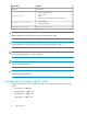
Convention Element Italic text Text emphasis • File and directory names • System output Monospace text • Code • Commands, their arguments, and argument values Monospace, italic Monospace, bold text text • Code variables • Command variables Monospace, bold text WARNING! Indicates that failure to follow directions could result in bodily harm or death. CAUTION: Indicates that failure to follow directions could result in damage to equipment or data.
Use the following values to calculate logical storage capacity (logical devices) for HP XP storage systems: • 1 KB (kilobyte) = 1,024 bytes • 1 MB (megabyte) = 1,0242 bytes • 1 GB (gigabyte) = 1,0243 bytes • 1 TB (terabyte) = 1,0244 bytes • 1 block = 512 bytes Rack stability Rack stability protects personnel and equipment. WARNING! To reduce the risk of personal injury or damage to equipment: • Extend leveling jacks to the floor. • Ensure that the full weight of the rack rests on the leveling jacks.
http://www.hp.com/go/selfrepair This product has no customer replaceable components. Product warranties For information about HP StorageWorks product warranties, see the warranty information website: http://www.hp.com/go/storagewarranty Subscription service HP strongly recommends that customers register online using the Subscriber's Choice website: http://www.hp.
1 Site preparation team and tasks The objective of a site preparation is to prepare your site for the successful and timely installation of the HP StorageWorks XP12000 Disk Array. Proper site preparation is vital for the reliability of the disk array. Site preparation involves a careful balance of equipment design criteria, site environmental variables, your business needs, and your budget constraints. In addition to this guide, other site preparation resources may be available to you.
1. If you have not printed a copy of this guide, you may want to print the “Site preparation checklist” and chapter 2. The aids are easier to use when printed, and printed copies provide a record for your files. 2. Carefully review chapter 2 to understand the site requirements. If you plan to connect external storage to the disk array, be sure to consider the requirements of that storage. See the documentation for the external system. 3.
* Check items Yes No Reference * Is the computer room free of any equipment servicing hazards (for example, electrical or data cables that obstruct access)? Preventing equipment servicing hazards, page 26 Is the existing floor plan documented? The space planning process, page 29 Has a new floor plan been developed to include the new array? The space planning process, page 29 * Does the new floor plan include adequate space for airflow and servicing needs? The space planning process, page 29 *
* Check items * Does the computer room support other environmental considerations (such as vibration and acoustics)? Yes No Reference Mechanical vibration specifications, page 38 Acoustic specifications, page 39 * Are two AC outlets, on different lines, available for the equipment? * Does the input voltage correspond to the DKC and DKU equipment specifications? * Are the input circuit breakers adequate for equipment loads? Branch circuit breakers, page 43 * Does the input frequency correspond t
• • • • Arranging for an electrician Adding or modifying air conditioning systems Making building alterations Placing an order for data communication equipment, including equipment to support the Internet-based remote support option The time between placing an equipment order and actual delivery can vary. Contact your HP representative to determine the best estimated delivery dates.
Site preparation team and tasks
2 Site requirements for the HP XP12000 Disk Array Your site must meet the following requirements before HP can deliver and install the system.
• • • • One One One One DKC DKC DKC DKC and and and and one DKU (R1) two DKUs (R1 and R2 or R1 and L1) three DKUs (R1, R2, and L1 or R1, L1, and L2) four DKUs (maximum configuration) Dimensions Dimensions for the DKC and DKU are shown in Table 2 and Table 3, respectively. Use the packaged values when determining delivery space requirements and unpackaged values during space planning. Table 2 Disk controller dimensions DKC Unpackaged DKC Packaged Dimension cm in cm in Width 78.2 30.8 89 35.
Minimum configuration Maximum configuration Cabinet Packaged kg lb kg lb 499 1100 853 1880 For each DKC or DKU shipment from the USA to locations outside the USA, add 59 kg (130 lb) for an international shipping crate. Within the USA, most shipments use a special carrier process in which frames are shipped without pallets, ramps, and cartons. In these cases, the packaged weight is the unpackaged weight plus 23 kg (50 lb). For upgrade DKU packaging (includes a ramp), add 29 kg (65 lb).
Product Description kg lb AE017A HP XP12000/10000 16-port EXSA CHIP 5.4 12 AE018A HP XP12000/10000 8-Port 1-Gbps NAS SW CHIP 6.5 14.3 AE019A HP XP12000/10000 8-Port 1-Gbps iSCSI CHIP 4.2 9.2 AE020A HP XP12000/10000 8-port 2-Gbps FC CHIP 4.6 10.1 AE021A HP XP12000/10000 8-port 4-Gbps FC CHIP 4.6 10.1 AE022A HP XP12000/10000 16-port 4-Gbps FC CHIP 5.0 11.0 AE023A HP XP12000/10000 32-port 4-Gbps FC CHIP 5.8 12.8 AE024A HP XP12000 DKC Power Supply 23.
Product Description kg lb AE051A HP XP12000 146-GB 10k-rpm Array Group, four disks 4.1 9 AE051AS HP XP12000 146-GB 10k-rpm Spare Disk 0.9 2 AE052A HP XP12000 146-GB 15k-rpm Array Group, four disks 4 8.8 AE052AS HP XP12000 146-GB 15k-rpm Spare Disk 1 2.2 AE053A HP XP12000 300-GB 10k-rpm Array Group 4 9 AE053AS HP XP12000 300-GB 10k-rpm Spare Disk 1 2 AE058A HP XP12000 300GB 15k-rpm Array Group, four disks 4 8.8 AE058AS HP XP12000 300GB 15k-rpm Spare Disk 1 2.
Part Number Description Unit Weight Quantity x = x = x = x = x = x = x = Total weight Total weight of your configuration Weight calculation example Part Number Description Unit Weight (lbs) Qty Total weight (lbs) AE002A HP XP12000 Disk Control Frame (DKC) 1300 x 1= 1300 AE002A #001 Three-phase 30A/60Hz for HP XP12000 DKC 50 x 1= 50 AE007A HP XP12000/10000 32-port 2-Gbps FC CHIP 13 x 2= 26 AE013A HP XP12000/10000 8-port FICON SW CHIP 13 x 1= 13 AE024A HP XP12000
Part Number Description AE051AS HP XP12000 146-GB 10k-rpm Spare Disk Unit Weight (lbs) Qty Total weight (lbs) 2x 4= 8 Total unpackaged weight of your configuration 3258.3 General computer room requirements The goal of a computer room is to maintain an ideal environment for computer equipment, including this system. Make sure your computer room adheres to all national and local building codes for a data center/computer room environment.
Safety requirements When making decisions concerning site safety, your first concern should be the safety of your personnel and then the safety of your equipment. Fundamental safeguards for disk arrays should include a site well away from any sources of potential damage. If you have any questions on site safety, consult your HP representative, your insurance carrier, and local building inspectors for safety recommendations.
WARNING! If metal is used in the construction of the computer room floor, ensure that there is a common ground connection between it and the ground or floor that it is built on to avoid possible build up of different voltage potentials. Noncompliance can result in serious injury to personnel and damage to equipment. Raised floor requirements A common method of preparing an adequate floor for a computer room is to construct a raised floor over the building floor.
Figure 2 Disk controller floor cutouts Figure 3 Disk unit floor cutout Estimating required floor load rating To estimate the load rating you need for your floor, consider the total weight of all of these items: 28 Site requirements for the HP XP12000 Disk Array
• • • • • The disk array (see “Weights” on page 20) Other equipment Furniture such as desks, chairs, and storage cabinets Computer room personnel Moving equipment, such as forklifts, dollies, and similar items The lower the floor load rating, the more clearance is required around the array to distribute the equipment weight correctly. If your computer room is too small to allow for minimum required clearance around the array, you may need to increase the floor load rating.
2. 3. Develop a new floor plan that includes the locations of: a. Immovable objects from your existing floorplan b. Walls c. The array with required clearance (see “Floor clearance requirements” on page 30) d. All other equipment, furniture, cabinets, racks, data communication equipment, and systems e. Floor cutouts (see “Raised floor cutout specifications” on page 27) f. Electrical outlets g.
3. Determine how much space you can assign to clearance C. For maintenance purposes, try to make C larger (100 cm) rather than smaller (0 cm). The smaller C is, the larger A and B must be. 4. In the table after the diagram, find the column that most closely matches the size of C. If your C value is between two table values, use the larger table value. Then, find the row for your floor load rating. Where the column and row intersect is the A+B value. 5.
Floor clearances, DKC only Figure 4 Floor clearances, DKC only Table 6 Overall floor clearance per floor load rating for a DKC only Floor load rating (kg/m2) If C=0A+B= If C=20 cm (7.9 in)A+B= If C=40 cm (15.8 in)A+B= If C=60 cm (23.6 in)A+B= If C=100 cm (39.
Floor clearances, DKC and one DKU Figure 5 Floor clearances, DKC and one DKU Table 7 Overall floor clearance by floor load rating for a DKC and one DKU Floor load rating (kg/m2) If C=0A+B= If C=20 cm (7.9 in)A+B= If C=40 cm (15.8 in)A+B= If C=60 cm (23.6 in)A+B= If C=100 cm (39.
Floor clearances, DKC and two DKUs Figure 6 Floor clearances, DKC and two DKUs Table 8 Overall floor clearance by floor load rating for a DKC and two DKUs Floor load rating (kg/m2) If C=0A+B= If C=20 cm (7.9 in)A+B= If C=40 cm (15.8 in)A+B= If C=60 cm (23.6 in)A+B= If C=100 cm (39.4 in)A+B= 500 120 90 60 40 0 450 170 130 100 70 30 400 240 200 160 130 80 350 340 280 240 200 140 300 500 430 370 320 240 NOTE: The clearance diagram shows a typical configuration.
Floor clearances, DKC and three DKUs Figure 7 Floor clearances, DKC and three DKUs Table 9 Overall floor clearance by floor load rating for a DKC and three DKUs Floor load rating (kg/m2) If C=0A+B= If C=20 cm (7.9 in)A+B= If C=40 cm (15.8 in)A+B= If C=60 cm (23.6 in)A+B= If C=100 cm (39.4 in)A+B= 500 160 120 80 50 0 450 230 180 140 100 50 400 320 260 210 170 100 350 460 380 320 270 190 300 660 570 490 420 320 NOTE: The clearance diagram shows a typical configuration.
Floor clearances, DKC and four DKUs Figure 8 Floor clearances, DKC and four DKUs Table 10 Overall floor clearance by floor load rating for a DKC and four DKUs Floor load rating (kg/m2) If C=0A+B= If C=20 cm (7.9 in)A+B= If C=40 cm (15.8 in)A+B= If C=60 cm (23.6 in)A+B= If C=100 cm (39.
Altitude requirements The maximum altitude for system operation is 3,000 meters. For nonoperational or storage situations, the maximum altitude is 4,000 meters. The minimum altitude for system operation is –60 meters. Air conditioning requirements Use separate computer room air conditioning duct work. If it is not separate from the rest of the building, it might be difficult to control cooling and air pressure levels.
You should not see any condensation in or around the disk array under any conditions. There is no procedure for recovery from moisture condensation.
Condition Specification Shipping and storage (in factory packing) Horizontal, incline impact: 1.22 m/sVertical, rotational edge: 0.1 m Acoustic specifications The acoustic emission specifications for the disk array are: • 8.
Product No. 40 Description Heat Output(kW) Power Consumption(kVA) AE003A HP XP12000 SVP High Reliability Sup. Kit 0.08 0.082 AE004A HP XP12000 Power Control I/F Kit for MF 0.002 0.002 AE006A HP XP12000/10000 16-port 2-Gbps FC CHIP 0.287 0.296 AE007A HP XP12000/10000 32-Port 2-Gbps FC CHIP 0.382 0.394 AE010A HP XP12000/10000 32-Port 4-Gbps FC CHIP 0.382 0.394 AE011A HP XP12000/10000 32-port 4-Gbps FC LW CHIP 0 0 AE013A HP XP12000/10000 8-Port FICON SW CHIP 0.346 0.
Product No. Description Heat Output(kW) Power Consumption(kVA) AE052A HP XP12000 146-GB 15k-rpm Array Group 0.092 0.1 AE053A HP XP12000 300-GB 10k-rpm Array Group–4 disk 0.092 0.1 AE058A HP XP12000 300-GB 15k-rpm Array Group–4 disk 0.092 0.1 AE050AS HP XP12000 73-GB 15k-rpm Spare Disk 0.022 0.024 AE051AS HP XP12000 146-GB 10k-rpm Spare Disk 0.023 0.025 AE052AS HP XP12000 146-GB 15k-rpm Spare Disk 0.023 0.025 AE053AS HP XP12000 300-GB 10k-rpm Spare Disk 0.023 0.
recommends that your site be evaluated for metallic particulate contamination before installation of electronic equipment. Data communication requirements Route data communication cables away from areas of high static electric fields created by power transformers and heavy foot traffic. Use shielded data communication cables that meet approved industrial standards to reduce the effects of external fields. Table 18 shows the data communication requirements for the XP disk array.
Line voltage Line voltage (AC) at the wall power outlet is a function of the local power utility and your building power distribution network. Voltages outside of the operating range of the HP system can cause intermittent system errors or a complete system shutdown. If required, an HP representative and your electrician can determine the current line voltage and make recommendations. See “Electrical specifications” on page 49 for specific AC line voltage requirements.
• An insulated grounding conductor that is identical in size and insulation material and thickness to the ungrounded branch-circuit supply conductors. It should be green, with or without yellow stripes, and is to be installed as a part of the branch circuit that supplies the unit or system. This means the ground conductor must be run in the same conduit, armored cable, or other cable bundle as the phase wires.
You are responsible for having the correct plugs and receptacles installed by an electrician in compliance with local electrical requirements and practices. See “Electrical specifications” on page 49 for specific plug and receptacle part numbers and ordering information. CAUTION: When installing the receptacles, the electrician must ensure that each receptacle has its own neutral (if required) and ground.
Uninterruptible power supply (UPS) Most disk array units are installed in data centers where a UPS strategy is already in place. However, if you are making your first large disk array purchase, you may need a separate UPS solution. CAUTION: This section discusses a product UPS. If you are planning or already have a site-wide UPS, HP recommends against using a product UPS powered by a site-wide UPS for the XP12000 disk array. Make sure your UPS satisfies the requirements in Table 21.
Delivery space requirements The delivery area must provide enough space and floor strength to support the packaged equipment cartons for the disk array. Refer to the packaged dimensions in “Dimensions” on page 20 and the packaged weights in “Weights” on page 20. CAUTION: Make sure that your doorways and hallways provide enough clearance to move the equipment safely from the delivery area to the computer room. Permanent obstructions such as pillars or narrow doorways can cause equipment damage.
Site requirements for the HP XP12000 Disk Array
3 Electrical specifications The detailed electrical specifications in this chapter are provided to help your site electrician perform any necessary electrical work related to site preparation. AC line voltage requirements Power specifications are presented in the following tables. Please note that in all tables 208 VAC is 60 Hz only. Units with only two power cords require only two circuit breakers.
Parameter 200 VAC 208 VAC 220 VAC 230 VAC 240 VAC 60 60 60 60 60 Dropout carry-through time at minimum line voltage (ms) Table 25 30-amp, 50 or 60 Hz, three-phase DKC power specifications Parameter 200 VAC 208 VAC 220 VAC 230 VAC 240 VAC 380 VAC 400 VAC 415 VAC Minimum operating voltage (VAC) 184 191 202 212 221 350 368 382 Maximum operating voltage (VAC) 212 220 233 244 254 403 424 440 13 12.5 11.9 11.3 10.9 6.9 6.5 6.
Parameter 200 VAC 208 VAC 220 VAC 230 VAC 240 VAC 30 30 30 30 30 4 4 4 4 4 60 60 60 60 60 Recommended circuit breakers (amps) Number of circuit breakers Dropout carry-through time at minimum line voltage (ms) Table 28 30-amp, 50 or 60 Hz, three-phase DKU power specifications Parameter 200 VAC 208 VAC 220 VAC 230 VAC 240 VAC 380 VAC 400 VAC 415 VAC Minimum operating voltage (VAC) 184 191 202 212 221 350 368 382 Maximum operating voltage (VAC) 212 220 233 244 254
Source Research, Inc. (SRI), 2160 Sunnydale Boulevard, Clearwater, FL 33765-2108, USA Telephone: (800) 356-0259. Contact: Erik Peterson, telephone extension 302, company website: http:// www.sourceresearch.com/index.cfm. Three-phase AC cabling for the USA (60 Hz) Each three-phase DKU has two main disconnect devices (two main breakers for dual power lines) so that AC power to the unit can be supplied from separate power distribution panels with two power supply cords.
The power cords provided with the disk array are nonshielded, type ST or equivalent with four #8 AWG (minimum) conductors terminated at one end with an assembled plug connector. Three-phase AC USA branch circuit requirements To protect the disk array, your building must be wired correctly. Each supply (“hot”) conductor must be protected by a short-circuit protective device and by an overcurrent protective device.
Figure 11 Connecting European three-phase power cords When connecting to 380 to 415 volt service, use a WYE configuration with neutral and ground conductors, in addition to the three-phase wires, for a total of five wires. WARNING! High leakage current can occur between the power supply and the unit. To avoid electrical shock, make the protective earth connection before the supply connections.
50-amp, single-phase power cords Each 50-amp XP12000 disk array rack has two power supply cords with attachment plug type Russellstoll 9P53U2. Figure 12 Fault-tolerant wiring with 50-amp, single-phase power cords Be sure to install Russellstoll 9C53U2 or 9R53U2W socket receptacles between the power distribution panel of the building and the power plugs for the unit.
The power cords provided with the disk array are nonshielded, type ST or equivalent with three #10 AWG (minimum) conductors terminated at one end with an assembled plug connector. Single-phase AC USA branch circuit requirements To protect the disk array, your building must be wired correctly. Each supply (“hot”) conductor must be protected by a short-circuit protective device and by an overcurrent protective device.
Figure 14 Connecting European single-phase power cords 30-amp single phase power cords for Europe Each 30-amp HP XP12000 disk array rack has four power supply cords. The power cords included with the unit are type H07RN-F or equivalent with three 6 square mm conductors. CAUTION: Be sure to connect the power cords to the distribution panel as shown in Figure 14. Improper wiring of the neutral conductor may cause damage to the disk array.
Electrical specifications
4 Delivery and unpacking The disk array equipment is shipped directly from HP. If the disk array is part of a system order, HP coordinates shipment from all HP locations so that all of the equipment arrives at your site at approximately the same time. When your equipment ships, HP provides you with carrier information and an expected delivery date. Factors beyond HP's control can cause delivery delays.
• Full packaging — consists of a pallet, wooden loading ramp, inner packaging, and outer corrugated carton assembly. • Full packaging with wooden crate — consists of full packaging encased in a wooden crate. Required personnel HP recommends that three physically able personnel be available to assist with offloading the disk array equipment from the pallet. Personnel must be knowledgeable and experienced with the safe handling of large, heavy, and sensitive computer equipment.
CAUTION: Any movement of the equipment by forklift should be done prior to unpacking. The carton assembly provides the most secure support of the equipment during movement. Transporting the equipment by forklift after the packaging carton has been removed is not advisable. CAUTION: The equipment racks are top heavy and contain very sensitive electronic and mechanical components.
1. If shipped in a wooden crate: a. Using an 11mm (7/16") ratchet or wrench, remove the six lag screws at the base of the crate. b. Using the claw end of a claw hammer, remove the crate clamps, and then remove the crate panels. WARNING! Crate clamps are under tension. Wear safety glasses and hold onto the clamp with your free hand during removal. Steps 2 through 5 refer to Figure 15. 1. Polyester bands 2. Pallet nails 3.
Figure 15 Removing the outer carton 2. Cut and remove the polyester bands. 3. Remove the nails attaching the carton to the pallet. 4. Remove the plastic carton fasteners. 5. Remove the carton. Steps 6 through 8 refer to Figure 16. 4. Accessory boxes 5. Ramp 6. Corner pads 7. Poly bag Figure 16 Unpacking the inner wrapping 6. Remove the accessory boxes, ramp, and corner pads. 7. Using a 6mm hex and 19mm wrench, remove the adapter plates that anchor the rack to the pallet. 8.
Delivery and unpacking
Glossary ACP Array control processor. On some HP XP models, such as the HP XP12000 Disk Array, the ACP handles the passing of data between the cache and the physical drives. On other HP XP models, such as the HP XP10000 Disk Array, this function is handled by the disk adapter on the MIX board. AL Arbitrated loop. AL-PA Arbitrated loop physical address. allocation The ratio of allocated storage capacity versus total capacity as a percentage.
channel processor (CHP) The processors located on the channel adapter (CHA). Synonymous with CHIP. command device A volume on the disk array that accepts Continuous Access or Business Copy control operations which are then executed by the disk array. control unit To organize the storage space attached to the DKC, you can group similarly configured logical devices (LDEVs) with unique control unit images (CUs). CUs are numbered sequentially.
failover Disconnecting a failed unit or path and replacing it with an alternative unit or path in order to continue functioning. FC Fibre Channel. FC-AL Fibre Channel arbitrated loop. FCP Fibre Channel Protocol. fence level A level for selecting rejection of a write I/O request from the host according to the condition of mirroring consistency. FICON IBM mainframe Fiber Optic Connection. GB Gigabytes. GLM Gigabyte link module. HA High availability. HBA Host bus adapter.
MIX A circuit board in the disk control unit that includes disk adapters and channel adapters for interfacing disk drives and the host to cache memory. mirroring consistency The consistency (usability) of data in a volume (for example, S-VOL). mm Millimeters. MR Magnetoresistive. ms, msec Milliseconds. mutual hot standby system Two servers that are poised to cover for each other if necessary. NAS Network attached storage.
RAID level A RAID Level is one of the ways that disk drives are grouped together to improve performance, data availability/reliability or both. RAID levels are defined from RAID0 to RAID6. HP StorageWorks Disk Arrays in the XP product family support RAID1, RAID5 and RAID6. Not all of these RAID levels are supported by all HP XP family members. Consult the owner's guide or your HP representative for the details of which RAID levels are supported by your specific HP XP disk array. RAM Random access memory.
Glossary
Index A AC line voltage, 43, 49 acoustics, 39 additional components, 21 air conditioning, 37 and dust control, 41 and metallic particulate contamination, 41 air pressure, 25, 41 airborne contaminants, 41 altitude, 37 antistatic carpeting, 29 containers, 25 audience, 9 B branch circuit requirements, 53, 54, 56, 57 branch circuits, 43 building codes, 25, 26, 43, 43 C C-Track, 42 cables, 29 and mechanical vibration, 38 and raised floors, 27 as safety hazards, 26, 30 Cat 5, 42 floor cutouts for, 27 in floorpl
document related documentation, 9 document conventions, 9 documentation HP website, 9 providing feedback, 12 dust control, 41 E earth ground requirements, 44 electrical interference, 46 electrical requirements, 43 electrical specifications, 49 electromagnetic interference, 46 electrostatic discharge.
P particulate contamination, metallic, 41 phone line, 42 physical specifications, 19 pollution control, 41 power receptacles, 44 requirements, 42, 49 uninterruptible, 46 consumption, 39 cords, 49 cords, floor cutouts for, 27 cords, single-phase for Europe, 56, 57 cords, single-phase for USA, 54, 56 cords, three-phase for Europe, 53 cords, three-phase for USA, 52, 53 line transients, 45 R rack stability warning, 11 raised floor, 29 See also floor, 27 receptacles, 44, 51 receptacles, power, 44 related docume