HP StorageWorks X9720 Network Storage System Controller User Guide This guide describes the components, basic operation, and troubleshooting of the SAS controller assembly in HP StorageWorks X9720 Network Storage Systems. For instructions to remove and replace controller hardware and to update controller firmware, see the HP StorageWorks X9720 Network Storage System Administration Guide.
Legal and notice information © Copyright 2009 Hewlett-Packard Development Company, L.P. The information contained herein is subject to change without notice. The only warranties for HP products and services are set forth in the express warranty statements accompanying such products and services. Nothing herein should be construed as constituting an additional warranty. HP shall not be liable for technical or editorial errors or omissions contained herein.
Contents 1 Overview .......................................................................................... 7 2 Components ...................................................................................... 9 Front panel components ............................................................................................................... 9 Hard drive bay numbers ........................................................................................................ 9 Rear panel components ........
Rack stability ............................................................................................................................ HP technical support ................................................................................................................. Customer self repair .................................................................................................................. Subscription service ................................................................................
Figures 1 Exploded view ........................................................................................................
Tables 1 LED Hard drive LED combinations ............................................................................. 16 2 POST codes ........................................................................................................... 19 3 Error codes ............................................................................................................ 19 4 Network Storage System controller parts list ...............................................................
1 Overview The HP StorageWorks X9720 Network Storage System controller includes the following hardware and firmware features: • 2U rack profile • 3.
Overview
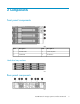
2 Components Front panel components Item Description Item Description 1 Heartbeat LED 3 UID button/LED 2 Fault ID LED 4 Hard drives Hard drive bay numbers Rear panel components X9720 Network Storage System Controller User Guide 9
Item Description Item Description 1 Power supply 1 5 SAS controller 2 2 Fan module 1 6 Fan module 2 3 Seven-segment display 7 Unit ID module (with Power/Standby button) 4 SAS controller 1 8 Power supply 2 Seven-segment display The seven-segment display displays Power On Self Test (POST) and system status information. During normal operation the display will read “on”.
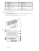
Item Description Item Description 1 Battery 1 6 Mini-SAS universal connector 4 2 Battery 2 7 Controller Status LED 3 Mini-SAS universal connector 5 8 Mini-SAS universal connector 3 4 Mini-SAS universal connector 6 9 Mini-SAS universal connector 1 5 Mini-SAS universal connector 2 Battery The battery provides uninterrupted power backup to the cache module in the event of a power failure for at least 96 hours.
Power/UID module The combined power/UID module allows you to power on/power off the enclosure, as well as identify the device and all additional cascaded devices. Item Description Item Description 1 UID button/LED 3 System fault LED 2 System heartbeat LED 4 Power/Standby button • To illuminate the UID LEDs on this and all cascaded devices, press the UID button. UID LEDs on the front and rear of the devices remain illuminated until the UID button is pressed a second time.
3 Basic operation Basic operating information includes: • Powering on / powering off • Updating system firmware Powering on/powering off IMPORTANT: System devices must be powered on and powered off in a specific sequence. If devices are powered on or powered off out of sequence, the server may not properly discover the storage or hard drives might be marked as failed. IMPORTANT: See the network storage system administration guide for detailed instructions.
IMPORTANT: See the network storage system administration guide for detailed instructions. NOTE: You can receive proactive support alerts, such as Customer Advisories, as well as updates on drivers, software, firmware, and customer replaceable components, using e-mail through HP Subscriber’s Choice. Sign up for Subscriber’s Choice at the following HP website: http://www.hp.com/go/myadvisory .
4 LED descriptions Front panel LEDs Item Description Status 1 Heartbeat LED Green—System activity Off—No system activity 2 Fault ID LED Amber—Fault condition exists Off—No fault condition exists 3 Unit Identification (UID) button/LED Blue—Identified Blinking blue—Active remote management Off—Not identified Hard drives See Hard drive LEDs 4 nl nl nl nl Hard drive LEDs X9720 Network Storage System Controller User Guide 15
Item Description 1 Fault/UID LED (amber/blue) 2 Online/activity LED (green) Table 1 LED Hard drive LED combinations Online/activity LED (green) Fault/UID LED (amber/blue) Interpretation On, off, or flashing Alternating amber and blue The drive has failed, or a predictive failure alert has been received for this drive; it also has been selected by a management application. On, off, or flashing Steadily blue The drive is operating normally, and it has been selected by a management application.
Online/activity LED (green) Fault/UID LED (amber/blue) Interpretation Off Amber, flashing regularly (1 Hz) A predictive failure alert has been received for this drive. Replace the drive as soon as possible. Off Off The drive is offline, a spare, or not configured as part of an array. NOTE: Predictive failure alerts are generated by system management software and occur only when the enclosure is connected to a Smart Array controller. The Network Storage System controller is a Smart Array controller.
Seven-segment display LEDs The seven-segment display indicates Power On Self Test (POST) and system status information. During normal operation, the display will read “on.” Item Description Use 1 Up button Scrolls the display up 2 Down button Scrolls the display down 3 Display Display area for POST and system status codes Codes consist of four characters, but only two characters are displayed at a time.
POST codes At power on, the enclosure goes through a series of tests called Power On Self Tests (POST). As each test runs, a code is displayed on the seven-segment display indicating the current test being run. Table 2 POST codes POST code Description SU Controller firmware has been unpacked and launched. S1 Port setup is complete. S2 Pause / Wait for Expander Discovery is complete. S3 Static Class Construction complete / Valid Stack Range has been set. S4 PCI express cores have been initialized.
Error code Description Required action Hn31–66 Hardware error—Controller error Log error, contact HP support, replace controller. Hn67 Hardware error—SAS expander error Log error, contact HP support, verify cabling. If error persists, replace controller.
Item Description Status 1 Battery LED Green solid—Healthy condition; battery fully charged Green rapid flash—Being recognized by controller; flashes flash rapidly when battery first installed and until recognized by controller Green slow flash—Discharging, cache module being powered by battery; action required Amber flashing—Fault condition 2 Controller LED Green — System activity Blinking amber — Fault condition Off — No system activity CAUTION: Do not remove a controller from the chassis while th
LED descriptions
5 Troubleshooting If the enclosure does not initialize If the enclosure does not initialize, check the seven-segment display for error codes. At power on, the enclosure goes through a series of Power On Self Tests (POST). As each test runs, a code is displayed on the seven-segment display, indicating the current test being run. See Seven-segment display LEDs. IMPORTANT: After a power failure or shutdown, the system automatically returns to last powered state (On or Off) when A/C power is restored. 1.
Is the system power LED amber? Answer Possible reasons Possible solutions No (green) System functioning properly. No action required Yes • The Power On/Standby button has not been pressed firmly or held long enough. • Firmly press the Power On/Standby button and hold for approximately three seconds. • The power supply may not be inserted properly, it may have a damaged connector, or it may have failed. • The system may have experienced a short. Controller firmware may be corrupted.
Is the SAS controller LED amber? Answer Possible reasons Possible solutions No (green) Functioning properly. No action required Yes • The controller has locked. • Check seven-segment display for error codes. See Chapter 4. • The controller has failed. • Other fault condition exists. • Make sure that the controller is seated properly by pressing the controller firmly into its bay after the handle has clicked in place. • Contact an authorized service provider for assistance.
• Open HP SIM or similar management software utility and inspect each physical drive in the array to confirm that no other drives have errors. • Be sure that the array has a current, valid backup. • Use replacement drives that have a capacity at least as great as that of the smallest drive in the array. The controller immediately fails drives that have insufficient capacity.
situation occurs, restart the server. The system may temporarily become operational long enough to allow recovery of unsaved data. In any case, locate the faulty drive, replace it, and restore data from backup. Handling hard drive failures IMPORTANT: See the network storage system administration guide for detailed instructions. If the controller was configured with hardware fault tolerance, complete the following steps after a hard drive failure: 1. Determine which physical drive failed.
Troubleshooting
6 Support and other resources Rack stability Rack stability protects personnel and equipment. WARNING! To reduce the risk of personal injury or damage to equipment: • Extend leveling jacks to the floor. • Ensure that the full weight of the rack rests on the leveling jacks. • Install stabilizing feet on the rack. • In multiple-rack installations, fasten racks together securely. • Extend only one rack component at a time. Racks can become unstable if more than one component is extended.
For more information about CSR, contact your local service provide, or see the CSR website: http:// www.hp.com/go/selfrepair. Subscription service HP recommends that you register your product at the Subscriber's Choice for Business website: http:/ /www.hp.com/go/e-updates. After registering, you will receive e-mail notification of product enhancements, new driver versions, firmware updates, and other product resources. HP websites For additional information, see the following HP websites: • http://www.hp.
A Parts catalog This product contains the parts illustrated in Figure 1 and listed in Table 4. Parts that are available for customer self repair (CSR) are indicated as follows: Mandatory CSR—Order the part directly from HP and repair the product yourself. On-site or return-to-depot repair is not provided under warranty. Optional CSR—Order the part directly from HP and repair the product yourself, or you can request that HP repair the product.
nl Table 4 Network Storage System controller parts list Item Description Spares part number CSR Mandatory Optional 1 3.
B Rack and environmental requirements Rack planning resources The rack resource kit ships with all HP-branded or Compaq-branded 9000, 10000, and H9 Series racks. For more information on the content of each resource, see the rack resource kit documentation. If you intend to deploy and configure multiple servers in a single rack, see the white paper on high-density deployment at the HP website: http://www.hp.com/products/servers/platforms.
Space and airflow requirements To allow for servicing and adequate airflow, observe the following space and airflow requirements when deciding where to install a rack: • Leave minimum clearance of 63.5 cm (25 in) in front of the rack. • Leave minimum clearance of 76.2 cm (30 in) behind the rack. • Leave minimum clearance of 121.9 cm (48 in) from the back of the rack to the back of another rack or row of racks. HP enclosures draw in cool air through the front door and expel warm air through the rear door.
Temperature requirements To ensure continued safe and reliable equipment operation, install or position the enclosure in a well-ventilated, climate-controlled environment. The maximum recommended ambient operating temperature (TMRA) for most enclosure products is 35°C (95°F). The temperature in the room where the rack is located must not exceed 35°C (95°F).
voltage and current rating for the cord should be greater than the voltage and current rating marked on the product. In addition, the diameter of the wire must be a minimum of 1.00 mm2 or 18 AWG, your maximum length may be up to 3.66 m (12 ft). WARNING! To reduce the risk of electric shock or damage to the equipment: • Do not disable the power cord grounding plug. The grounding plug is an important safety feature.
C Electrostatic discharge Preventing electrostatic discharge To prevent damaging the system, be aware of the precautions you need to follow when setting up the system or handling parts. A discharge of static electricity from a finger or other conductor may damage system boards or other static-sensitive devices. This type of damage may reduce the life expectancy of the device. To prevent electrostatic damage: • Avoid hand contact by transporting and storing products in static-safe containers.
Electrostatic discharge
D Specifications Environmental specifications Specification Value Temperature range Operating1 Storage 10°C to 35°C (50°F to 95°F) Maximum rate of change is 10º C/Hr (18º F/Hr) -30°C to 60°C (-22°F to 140°F) Maximum rate of change is 20º C/Hr (36º F/Hr) Relative humidity2 10% to 90% relative humidity (Rh) Operating 28º C (82.4º F) maximum wet bulb temperature non-condensing 5% to 95% relative humidity (Rh) Storage 38.7º C (101.
Enclosure specifications Specification Value Height 8.8 cm (3.47 in) Depth 59 cm (23.25 in) Width 44.80 cm (17.64 in) Weight (maximum) 24.6 kg (57.7 lb ) Weight (no drives installed) 17.14 kg (37.
E Regulatory compliance notices Regulatory compliance identification numbers For the purpose of regulatory compliance certifications and identification, this product has been assigned a unique regulatory model number. The regulatory model number can be found on the product nameplate label, along with all required approval markings and information. When requesting compliance information for this product, always see this regulatory model number.
interference will not occur in a particular installation. If this equipment does cause harmful interference to radio or television reception, which can be determined by turning the equipment off and on, the user is encouraged to try to correct the interference by one or more of the following measures: • Reorient or relocate the receiving antenna. • Increase the separation between the equipment and receiver.
This Class B digital apparatus meets all requirements of the Canadian Interference-Causing Equipment Regulations. Cet appareil numérique de la classe B respecte toutes les exigences du Règlement sur le matériel brouilleur du Canada. European Union regulatory notice This product complies with the following EU Directives: • Low Voltage Directive 73/23/EEC • EMC Directive 89/336/EEC CE Compliance of this product is valid only if powered with the correct HP-provided and CE marked AC adapter.
Frequency availability for 802.11a or 802.11h Wireless LAN is not currently harmonized throughout the European Union. For compliance requirements, users should verify with their supplier, local HP office or Telecommunications authority. Disposal of waste equipment by users in private households in the European Union This symbol on the product or on its packaging indicates that this product must not be disposed of with your other household waste.
Korean notice Class A equipment Class B equipment Power cord statement for Japan X9720 Network Storage System Controller User Guide 45
Regulatory compliance notices
Index D A Declaration of Conformity, 42 diagnostic steps, 23 recognizing hard drive failure, 25 documentation providing feedback, 30 airflow requirements, 34 B battery description, 11 disposal of, 11 bays of hard drives, 9 BSMI notice, 44 E C cables, 42 cache module description, 11 caching methods posted-write, 11 read-ahead, 11 Canadian notice, 42 Class A equipment, 42 Class B equipment, 42 Class A equipment Canadian n notice, 42 Federal Communications Commission notice, 41 Class B equipment Canadian
help, obtaining, 29 HP technical support, 29 J Japanese notice, 44 K Korean notices, 45 L LED descriptions fan module, 20 front panel, 15 hard drives, 15 power supply, 17 SAS controller, 20 Seven-segment display, 18 UID module, 21 LEDs troubleshooting, 17 N notices BSMI, 44 Canadian, 42 European Union, 43 FCC, 41 Japanese, 44 Korean, 45 O optimum environment, 33 overview, of Network Storage System controller, 7 P parts replaceable, 31 POST codes, 19 power cord statement for Japan, 45 power cords, 35 p
websites customer self repair, 29 HP, 30 HP Subscriber's Choice for Business, 30 X9720 Network Storage System Controller User Guide 49