
HP StorageWorks ExDS9100c/X9720 Storage System Controller (496785-002, December 2009)
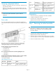
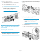

Table Of Contents
- ExDS9100c/X9720 Storage System Controller
- Customer self repair (CSR)
- Before you begin
- Verifying component failure
- Preparation
- Step 1: Removing the failed controller
- Step 2: Transferring the cache module and batteries
- Step 3: Installing the replacement controller
- Confirming the firmware version
- Verifying component status
- Returning the failed component
- Additional information

Verifying component failure
• Check the controller LED on the rear of the chassis. If the LED is am-
ber, it indicates a failure.
• Check for an error code on the seven-segment display on the rear
of the chassis and take appropriate action. Error codes are described
in Error codes.
IMPORTANT:
See the storage system administration guide for additional
information.
Error codes
The seven-segment display indicates Power On Self Test (POST) and
system status information. During normal operation, the display will read
“on.”
Error codes consist of four character, but only two characters are
displayed at a time. Pressing the up or down arrow button on the
seven-segment display shows the remaining characters.
The first character represents the domain code:
• C—Configuration error
• F—Firmware error
• H—Hardware error
The second character indicates the controller signalling the error:
• 1—Controller 1
• 2—Controller 2
The third and fourth characters indicate the specific error on the controller:
(Displayed by pressing the up or down arrow button on the
seven-segment display.)
Table 1 Hardware error codes
ActionDescriptionError code
Log error, contact HP support,
replace indicated controller.
Hardware error—Con-
troller error
Hn00–Hn29
Log error, contact HP support,
replace cache module.
Hardware er-
ror—Fatal ECC error
Hn30
Log error, contact HP support,
replace controller.
Hardware error—Con-
troller error
Hn31–66
Log error, contact HP support,
verify cabling. If error per-
sists, replace controller.
Hardware error—SAS
expander error
Hn67
Preparation
1. Ensure that a known, good backup of the data is available.
2. Schedule a maintenance window.
3. From the servers, stop all access to the enclosure.
nl
(Optional in dual controller configurations.)
Step 1: Removing the failed controller
CAUTION:
Never remove a controller from the chassis while the controller
status LED is green. Removing an active controller (green LED)
can result in data loss.
1. From the servers, stop all access to the enclosure.
nl
(Optional in dual controller configurations.)
2. Label each cable connected to the controller with its port number.
This ensures proper re-connection after completing the replacement.
3. Remove the cables from the controller.
Page 2