HP X9000 File Serving Software Installation Guide Abstract This document describes how to install the X9000 File Serving Software. It is intended for HP Services personnel who configure X9000 series Network Storage systems at customer sites. For upgrade information, see the administration guide for your system. For the latest X9000 guides, browse to http://www.hp.com/support/manuals.
© Copyright 2009, 2011 Hewlett-Packard Development Company, L.P. Confidential computer software. Valid license from HP required for possession, use or copying. Consistent with FAR 12.211 and 12.212, Commercial Computer Software, Computer Software Documentation, and Technical Data for Commercial Items are licensed to the U.S. Government under vendor's standard commercial license. The information contained herein is subject to change without notice.
Contents 1 Configuring the management console and file serving nodes on X9300/X9320 systems........................................................................................................6 Installation checklist..................................................................................................................6 Getting started.........................................................................................................................7 Configuring the management console.....
Configuring CIFS shares (optional)............................................................................................45 Configuring other X9000 Software features................................................................................45 5 Adding Linux X9000 clients.......................................................................47 Prerequisites for installing the Linux X9000 client.........................................................................47 Installation procedure.......
HP websites...........................................................................................................................78 Glossary....................................................................................................
1 Configuring the management console and file serving nodes on X9300/X9320 systems Installation checklist Step Task More information 1. Set up the HP 2000 G2 Modular Smart Array or P2000 G3 MSA System (X9320 systems) The array documentation is on http:// www.hp.com/support/manuals under storage > Disk Storage Systems 2. Set up iLO on the ProLiant servers The server documentation is on http:// www.hp.com/support/manuals under servers > ProLiant ml/dl and tc series servers 3.
Getting started The initial installation, performed at the factory, installs the operating system and X9000 Software on the management console and file serving nodes. HP Services personnel configure the management console and file serving nodes at the customer site. This is the default installation and configuration method. HP Services also configures Linux X9000 clients, up to 10 clients total. IMPORTANT: Before starting the installation, check for any patches on the HP kiosk: http:// www.software.hp.
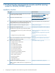
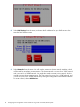
4. The Management Console Configuration Menu lists the configuration parameters that you need to set. 5. Select Hostname from the menu, and enter the hostname of this server.
6. Select Time Zone from the menu, and then press the up or down arrow keys to select your time zone. 7. Select Default Gateway from the menu, and enter the IP Address of the host that will be used as the default gateway.
8. Select DNS Settings from the menu, and enter the IP addresses for your DNS servers. Also enter the DNS domain name. 9. Select Networks from the menu. You will need to create one cluster network interface, which will be used for intracluster communication. The cluster network is bond0 for a 1GbE network and is bond1 for a 10GBE network. You might also need to create a user network, which is used for server-to-client communication.
You are creating a bonded interface for the cluster network. Select Ok on the Select Interface Type dialog box. Enter a name for the interface. (For a 1GbE network, the cluster interface is bond0. For a 10GbE network, the cluster interface is bond1.) Also specify the appropriate options and slave devices. Use mode 6 bonding for a 1GbE network, and mode 1 bonding for a 10GbE network.
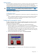
10. When the Configure Network dialog box reappears, select bond0 or bond1, as appropriate for your network.
11. To complete the bond configuration, enter a space to select the Cluster Network role. Then enter the IP address and netmask information that the network will use. Repeat this procedure to create a bonded user network (typically bond1, or a VIF on bond1 for a 10GbE network that is configured in X9000 Software) and any custom networks as required. 12. Select NTP Servers from the menu, and enter the IP addresses or hostnames for the primary and secondary NTP servers.
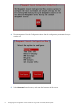
13. Select Set Cluster VIFs from the menu to configure virtual interfaces for the cluster. On the Configure Cluster Virtual Interfaces dialog box, enter the virtual IP addresses and netmasks for the cluster and user networks. 14. The Confirm Management Console Configuration screen lists the values entered for the management console. You can change the values if needed. When you select Commit, the values are applied. Networking is set up, and the management console software starts.
Creating a template for configuring file serving nodes To simplify configuring your file serving nodes, you can create a template to apply to each node. The template specifies the IP address that the nodes will use to access the management console, defines how hostnames will be generated for the nodes, and specifies a range of IP addresses to be used when configuring networks on the nodes.
3. 16 Select Time Zone from the menu, and then use the up or down arrow keys to select your time zone.
4. Select Default Gateway from the menu, and enter the IP Address of the host that will be used as the default gateway. 5. Select Management Console from the menu. The IP address that you specified earlier for the management console will be filled in. 6. Select Hostname Template from the menu. Each File Serving Node must have a unique hostname. The hostname template generates the names automatically, based on the naming scheme that you select.
The parameters in the naming schemes, when enclosed in braces ({...}), expand in the following manner: • number num: The number of File Serving Nodes in the cluster. NOTE: When using the number format, allow each File Serving Node to register before logging in to the next system.
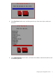
8. Select Network Templates from the menu. On the Configure Network Templates screen, select to create a cluster network. Select Ethernet Interface to begin configuring the interface.
Enter the Ethernet devices that will be used to create the bonded interface, as described in the following steps. Select Bonded Interface as the interface type.
Identify the bonded interface and enter the appropriate bond options and slave devices. Use mode 6 bonding for 1GbE networks and mode 1 bonding for 10GbE networks. Select the role for the network and enter the IP address information the network will use.
9. Using the procedure in the above step, create templates for user and custom networks as necessary. 10. When you have completed your entries on the Cluster Configuration Menu, select Continue. 11. Verify the template on the confirmation screen and select Commit. The values are applied when you configure each file serving node. Using the template to configure file serving nodes This procedure applies the template that you created to the file serving nodes. Perform this procedure on each node.
3. The Configuration Wizard attempts to discover management consoles on the network and then displays the results. Select the appropriate management console for this cluster. NOTE: If the list does not include the appropriate management console, or you want to customize the cluster configuration for the File Serving Node, select Cancel. Go to “Configuring file serving nodes manually” (page 24) for information about completing the configuration. 4.
Completing the installation For more information, see the following: • “Post-installation tasks” (page 44) • “Adding Linux X9000 clients” (page 47) Configuring file serving nodes manually Use this procedure to configure file serving nodes manually instead of using the template. 1. Log into the system as user root (the default password is hpinvent). 2. When the System Deployment Menu appears, select Join an existing cluster. 3.
4. The File Serving Node Configuration Menu appears. 5. The Cluster Configuration Menu lists the configuration parameters that you need to set. Use the up and down arrow keys to select an item in the list. When you have made your select, press Tab to move to the buttons at the bottom of the dialog box, and press the spacebar to go to the next dialog box. 6. Select Management Console from the menu, and enter the IP address of the management console.
7. Select Hostname from the menu, and enter the hostname of this server. 8. Select Time Zone from the menu, and then use the up or down arrow keys to select your time zone.
9. Select Default Gateway from the menu, and enter the IP Address of the host that will be used as the default gateway. 10. Select DNS Settings from the menu, and enter the IP addresses for the primary and secondary DNS servers that will be used to resolve domain names. Also enter the DNS domain name.
11. Select Networks from the menu. Select to create a bond for the cluster network. You are creating a bonded interface for the cluster network; select Ok on the Select Interface Type dialog box.
Enter a name for the interface. The cluster interface is bond0 for a 1GbE network and bond1 for a 10GbE network. Also specify the appropriate options and slave devices. Use mode 6 bonding for 1GbE networks and mode 1 bonding for 10GbE networks. 12. When the Configure Network dialog box reappears, select bond0.
13. To complete the bond configuration, enter a space to select the Cluster Network role. Then enter the IP address and netmask information that the network will use. The user network is a VIF on bond1 for 10GbE network that in configured in X9000 Software. Repeat this procedure to create a bonded user network (typically bond1) and any custom networks as required. 14. When you complete your entries on the File Serving Node Configuration Menu, select Continue. 15.
Completing the installation For more information, see the following: • “Post-installation tasks” (page 44) • “Adding Linux X9000 clients” (page 47) Configuring file serving nodes manually 31
2 Installing and configuring X9720 systems IMPORTANT: The Create a X9720 cluster option on the System Deployment Menu is for factory use only. To install and configure X9720 systems at a customer site, use the instructions in this chapter. Installation checklist Step Task More information 1. Redeem X9000 File Serving Software Licenses. “Redeem X9000 File Serving Software licenses” (page 33) 2.
Step Task More information 9. Perform post-installation tasks: “Post-installation tasks” (page 44) • Configure Ibrix Collect. • Create file systems. • Set up NFS exports (optional). • Set up CIFS shares (optional). • Set up HTTP/HTTPS (optional). • Set up FTP/FTPS (optional). • Remote replication (optional). • Data retention and validation (optional). • Software snapshots (optional). • Data tiering (optional). • NDMP (optional). • Insight Remote Support. 10. Configure Linux X9000 clients (optional).
Boot server blades NOTE: If the server blades were powered on when the previous step completed (that is, one or more capacity blocks powered on after the server blades), cycle the power on all server blades again. Complete the following steps: 1. Connect a LAN cable from a laptop to a port on one of the ProCurve switches. Set the TCP/IP properties of the laptop LAN port to address 172.16.3.200, subnet 255.255.248.0. You should now be able to make an ssh connection to the blade servers.
X9720 bonding. Mode 4 (LACP) should not be used on X9720 systems as LACP packets are handled by the VC Flex 10 and are not forwarded to the blade servers. Properly configured, this provides a fully redundant network connection to each blade. A single failure of NIC, Virtual Connect module, uplink, or site network switch will not fail the network device.
2. Create an ifcfg-ethn file for each interface in bond1. The default for bond1 uses eth1 and eth2. Edit the ifcfg-eth1 file to appear as follows, ensuring that MASTER and SLAVE are set properly. Assuming the HWADDR for eth1 is 78:e7:d1:64:3a:1c: DEVICE=eth1 USERCTL=no ONBOOT=yes MASTER=bond1 SLAVE=yes BOOTPROTO=none HWADDR=78:e7:d1:64:3a:1c 3.
MII Status: up MII Polling Interval (ms): 100 Up Delay (ms): 100 Down Delay (ms): 0 Slave Interface: eth1 MII Status: up Link Failure Count: 0 Permanent HW addr: 78:e7:d1:64:3a:1c Slave Interface: eth2 MII Status: up Link Failure Count: 0 Permanent HW addr: 78:e7:d1:64:3a:19 View the configuration You can check the IP, netmask and broadcast configuration with the ifconfig command.
> > Set the time zone Run timeconfig to set the correct time zone for the system location. Install the agile management console Install the agile management console on all nodes in the cluster. The agile management console is active on the first node installed and passive on the other nodes. Run the following command on each node: • .
# ibrix_nic –t –n bond1 –h kudos1 # ibrix_nic –t –n bond1 –h kudos2 # ibrix_nic –t –n bond1 –h kudos3 Completing the installation For more information, see the following: • “Post-installation tasks” (page 44) • “Adding Linux X9000 clients” (page 47) Changing IP addressing for the private network (optional) NOTE: This procedure is for use only on systems with a stand-alone, dedicated management console configuration prior to installing the agile management console.
12. Edit the bond0 configuration file and change the IPADDR parameter to the new address: vi /etc/sysconfig/network-scripts/ifcfg-bond0 13. Restart the network service on all servers: pdsh -a service network restart You will be disconnected. NOTE: If it is not possible to ping the bond0 interface on each server after the network restarts, it will still be possible to connect a browser session to the iLO to get a console session to fix the issue, or you can use the KVM console. 14.
3 Configuring virtual interfaces for client access X9000 Software uses a cluster network interface to carry management console traffic and traffic between file serving nodes. This network is configured as bond0 when the cluster is installed. For clusters with an agile management console configuration, a virtual interface is also created for the cluster network interface to provide failover support for the console.
# # # # ibrix_nic ibrix_nic ibrix_nic ibrix_nic –b –b –b –b –H –H –H –H node1/bond1:1,node2/bond1:2 node2/bond1:1,node1/bond1:2 node3/bond1:1,node4/bond1:2 node4/bond1:1,node3/bond1:2 Configuring NIC failover NIC monitoring should be configured on VIFs that will be used by NFS, CIFS, FTP, or HTTP. Use the same backup pairs that you used when configuring standby servers.
HTTP. When you create a virtual host on the Create Vhost dialog box or with the ibrix_httpvhost command, specify the VIF as the IP address that clients should use to access shares associated with the Vhost. X9000 clients. Use the following command to prefer the appropriate user network. Execute the command once for each destination host that the client should contact using the specified interface. ibrix_client -n -h SRCHOST -A DESTNOST/IFNAME For example: ibrix_client -n -h client12.mycompany.
4 Post-installation tasks Configuring data collection with Ibrix Collect Ibrix Collect is a log collection utility that gathers relevant information for diagnosis by HP Support. For information about configuring Ibrix Collect, see “Collecting information for HP Support with Ibrix Collect” in the administrator guide for your system. Using the management console GUI The GUI is a browser-based interface to the X9000 management console.
Configuring NFS exports (optional) The GUI provides the easiest way to configure NFS exports. For more information, see “Using NFS” in the HP X9000 File Serving Software File System User Guide. NOTE: On the Export Filesystem via NFS dialog box, change the path as needed to meet customer requirements. The default value for path is the root directory of the file system. The other default values on the dialog box should be adequate for most sites.
• Block snapshots • Data tiering See the administrator guide for your platform for information about configuring NDMP.
5 Adding Linux X9000 clients Linux X9000 clients run applications that use the file system. The clients can read, write, and delete files by sending requests to File Serving Nodes. This chapter describes how to install, configure, and register the clients. Prerequisites for installing the Linux X9000 client Before installing the client software, do the following: • Install a supported version of the operating system, accepting all packages. Do not add or delete packages from the package list.
Registering Linux X9000 clients Linux X9000 clients must be registered manually with the management console before they can mount a file system. To register a client using the CLI, use the following command: /bin/ibrix_client -a -h HOST -e IPADDRESS For example, to register client12.hp.com, which is accessible at IP address 192.168.2.12: /bin/ibrix_client -a -h client12.hp.com -e 192.168.2.
/bin/ibrix_hostgroup -n -g clients -A s2.hp.com/eth3 Uninstalling Linux X9000 clients IMPORTANT: Be sure to unmount the file system from X9000 clients before uninstalling the clients. To uninstall a client, complete the following steps: 1. On each X9000 client, run the following command to unmount the file system: /bin/ibrix_lwumount -f You can also use the management console GUI to perform the unmount. 2.
6 Using ibrixinit The ibrixinit utility is used to install or uninstall the Fusion Manager, file serving node, and statstool packages on a file serving node. It can also be used to install or uninstall the X9000 client package on a Linux client. Synopsis Install the Fusion Manager, file serving node, and statstool packages on a file serving node: .
Option Description -m Specifies the Cluster virtual interface network mask for Fusion Manager -tc Installs or uninstalls the Linux X9000 client -u Uninstalls Fusion Manager, file serving node software, and statstool components, including the RPMs, on this file serving node -v Specifies the Cluster virtual interface IP address for Fusion Manager -w Specifies a port for Fusion Manager to listen on for webserver communication -h Displasy a help message for this com
7 Network best practices for X9300 and X9320 systems The X9300 series storage appliances can use three networks for operation: the cluster network, user network, and management network. During the initial installation and setup of the storage appliance, it is configured for a 1GbE network or a 10GbE network in accordance with the best practices described in this chapter. NOTE: HP recommends that you use the agile management console configuration.
The following diagram shows the network cabling for an X9300/X9320 1GbE system.
Network switches in the X9300 Storage System base rack (AW546B) The X9300 base rack includes two HP ProCurve 2910al-48G network switches. These switches are equipped with the 10GbE interconnect modules and provide: • 96x 1GbE network ports (48 ports per switch) • 4x 10GbE CX4 ports (2 ports per switch) for switch interconnection The cluster network switches are “stackable,” and when connected together through the 10GbE CX4 interconnect ports, the pair operate as a single switch.
NOTE: An X9300 Gateway pair can be substituted for an X9320 system. Factory cabling of the cluster network For Rev B models of the X9320 system (introduced in April 2010), the cluster network is cabled in the factory if the system is ordered with factory rack integration. The cluster network is cabled per the cluster network cabling diagram shown in “Onsite cabling of the cluster network” (page 55). NOTE: Rev A models of the X9320 system did not include the dual 48-port cluster network switches.
Scaling out to multiple racks Two or more X9320/X9300 cluster racks can be interconnected for scale out. As long as the racks and networks are cabled and configured as shown in this chapter, the scale out can be accomplished by chaining the cluster network switches together. Interconnecting the switches allows the cluster network to span racks. As a result, all IP addresses on the cluster network across both racks must be unique.
Configuring the NIC ports and network addresses on the 1GbE cluster/management network The cluster network NIC ports on the file serving nodes/Management Servers and the optional Dedicated Management Server are bonded to provide path redundancy and higher aggregate performance. The following table describes how to configure the bonds and provides a suggested IP address plan for the cluster network. ALB - mode 6 bonding is the default recommended bonding mode for a 1GbE network.
Component Optional Dedicated Management Server NIC port Bond eth7 bond1:3 Bond mode IP address/subnet mask eth2 eth3 bond1 ALB — mode 6 10/10.1.100/ 255.255.255.0 eth4 eth5 Using 10GbE networks The following logical network diagram shows a system using a 10GbE network. The following diagram shows network cabling for a system using a 10GbE network.
Configuring a 10GbE network In 10GbE environments with demanding workloads, system performance can be maximized by configuring the cluster network to operate over the 10GbE network ports in the file server/Management nodes. The objective is to enable inter-segment file I/O through the 10GbE interfaces. Even with a 10GbE cluster network, a 1GbE management network is still required and should be configured as shown because the iLO interfaces and MSA management ports are all 1GbE interfaces.
To separate the private cluster network traffic from client file I/O traffic (NFS, CIFS, and so on), virtual network interfaces (VIFs) should be created on the 10GbE bond (bond 1) for NFS, CIFS, FTP, HTTP, and X9000 shares on each server. The client systems will access the file system through the VIFs only. The cluster members (file serving nodes and, optionally, Dedicated Management Server) will use the Base Address of the 10GbE bond (bond 1) on each server for cluster communication and operation.
Component MSA 2 (if present) Optional Dedicated Management Server NIC port Bond Bond mode IP address/subnet mask controller B 192.168.1.12 / 255.255.255.0 controller A 192.168.1.13 / 255.255.255.0 controller B 192.168.1.14 / 255.255.255.0 eth0 bond0 ALB — mode 6 192.68.1.100 / 255.255.255.0 eth1 iLO 192.68.1.200 / 255.255.255.0 The following figure shows the network handling cluster management traffic and NFS/CIFS traffic.
:::::::::::::: # Broadcom Corporation NetXtreme II BCM5709 Gigabit Ethernet DEVICE=eth1 HWADDR=78:e7:d1:8d:e9:56 ONBOOT=no BOOTPROTO=none BROADCAST= IPADDR= MASTER=bond1 NETMASK= SLAVE=yes USERCTL=no :::::::::::::: ifcfg-eth2 :::::::::::::: # Broadcom Corporation NetXtreme II BCM5709 Gigabit Ethernet DEVICE=eth2 HWADDR=78:e7:d1:8d:e9:58 ONBOOT=no BOOTPROTO=none BROADCAST= IPADDR= MASTER=bond1 NETMASK= SLAVE=yes USERCTL=no :::::::::::::: ifcfg-eth3 :::::::::::::: # Broadcom Corporation NetXtreme II BCM5709 G
8 Network best practices for X9720 systems This document is intended for system consultants, system engineers, onsite installers, HP Technical Support, and customers of the X9720 Network Storage System. Overview of the X9720 network The X9720 series storage network communication is comprised of several networks or network types, or even more precisely, it can be designated by named sets of IP addresses.
IP addressing schemas The X9720 is shipped from the factory with the following configuration and must be modified to the customer’s environment. Component NIC port Bond/VIF Bond mode Network/IP Type IP Address Management console eth0 bond0 active-backup mode=6 Cluster 172.16.3.1 Management 172.16.4.1 Cluster 172.16.3.2 Management 172.16.4.2 OA Management 172.16.1.1 VC Manager Management 172.16.2.
Following is a sample final network configuration with the public network based on a 10.10.135.0 subnet: Management Network (private): 172.16.0.0/255.255.248.0 Cluster and User Network: 10.10.135.0/255.255.255.0 Gateway IP: 10.10.135.1 Component NIC port File serving node 1 eth0 Bond/VIF Bond Mode Nework/IP Type IP Address bond0 active-backup mode=1 Management 172.16.3.1 Cluster 10.10.135.11 eth3 eth1 nl bond1 bond1:0 active-backup mode=1 Management Console 10.10.135.
The following example shows an X9720 cabled to a redundant switch pair. Each Virtual Connect bay connects to a separate switch to provide for VC and external switch redundancy. Following are examples of redundant switch configurations for the X9720: • Two independent switches • Two physical switches that are part of a clustered pair • Two blades within a redundant switch chassis Cabling examples including LACP link aggregation The X9720 supports LACP/802.
Clustered switch pairs If the redundant switch pair is part of a clustered or stackable switch pair, LACP links can be formed between the switch pair, and can have performance benefits by crossing the links between each pair of switches. Refer to your switch documentation to determine whether LACP links can be formed between separate physical blades or switches within the clustered configuration, and for information about performance recommendations.
Bonding modes for file serving nodes The recommended file server bonding for X9720 configurations is mode=1 (that is, active-backup). Previously, the advised bonding mode was mode=6, or active-alb. However, this mode may cause problems and sporadic failures in some X9720 configurations. In addition, there is likely no performance benefit to using this mode in the X9720 configuration. Therefore, it is recommended that users configure their systems to be mode=1, which is also known as active-backup.
Sample files and command output This section includes the following: • An example of a /etc/modprobe.conf file • Output from /proc/net/bonding/bond* • IP address configuration files for cluster and user IP addresses • Output from the ibrix_nic command Sample /etc/modprobe.conf file # hostname x965s1 # more /etc/modprobe.
MII Polling Interval (ms): 100 Up Delay (ms): 100 Down Delay (ms): 0 Slave Interface: eth1 MII Status: up Link Failure Count: 0 Permanent HW addr: 78:e7:d1:57:e2:cc Slave Interface: eth2 MII Status: up Link Failure Count: 0 Permanent HW addr: 78:e7:d1:57:e2:c9 IP address configuration files for cluster and user IP addresses # cd /etc/sysconfig/network-scripts # more ifcfg-bond* ifcfg-eth* :::::::::::::: ifcfg-bond0 :::::::::::::: DEVICE=bond0 ONBOOT=yes BOOTPROTO=none IPADDR=172.16.3.1 NETMASK=255.255.248.
SLAVE=yes HWADDR=78:e7:d1:57:e2:c9 :::::::::::::: ifcfg-eth3 :::::::::::::: DEVICE=eth3 BOOTPROTO=none ONBOOT=yes MASTER=bond0 SLAVE=yes HWADDR=78:e7:d1:57:e2:cd Output from ibrix_nic # ibrix_nic -i -h x965s1 | egrep -v "Rx|Tx" Nic: x965s1/bond1:2 =================== Host : x965s1 Interface : bond1:2 Type : User State : Up, LinkUp IP_Address : 10.10.135.31 MAC_Address : 78:e7:d1:57:e2:cc Netmask : 255.255.255.0 Gateway : Broadcast Address : 10.10.135.
Duplex LINKMON Monitored By Collisions LastReported # ibrix_nic –l HOST IFNAME ------ -----x965s1 bond1 x965s1 bond1:2 x965s1 bond1:3 x965s2 bond1 x965s2 bond1:2 x965s2 bond1:3 72 : : : : : No TYPE ------Cluster User User Cluster User User 0 3 Days 19 Hrs 16 Mins 45 Secs ago STATE ---------------Up, LinkUp Up, LinkUp Inactive,Standby Up, LinkUp Up, LinkUp Inactive,Standby Network best practices for X9720 systems IP_ADDRESS -----------10.10.135.11 10.10.135.31 10.10.135.12 10.10.135.
9 Setting up InfiniBand couplets InfiniBand is supported for X9300 and X9320 systems. The following logical network diagram shows an InfiniBand configuration. The following diagram shows network cabling for an InfiniBand configuration.
Downloading and installing the InfiniBand software HP supports Mellanox OFED v1.5.2 for use with X9300/X9320 systems. You can download the software from the HP Software and Drivers web site: http://www8.hp.com/us/en/support-drivers.html On the web site, search for offed 1.5.2 and then select the RHEL 5U5 link. The link opens the Mellanox InfiniBand Driver for Operating System Red Hat Enterprise Linux Version 5 Update 5 web page. Click the Installation Instructions tab. Install OFED 1.5.
Installing the driver CAUTION: OFED 1.5.2 overwrites pre-existing /lib/modules vital to X9000 Software and NFS protocol. The InfiniBand driver exchanges these modules on install as InfiniBand wants RPC and NFS to go over RDMA instead of IP. You will need to manually move mv(7) updated kernel module files after the installation of the OFED stack.
/sys/class/net/ib0 "echo connected > /sys/class/net/ib0/mode" "ifconfig ib0 mtu 65520" NOTE: For Windows WinOF (OFFED) IB client connectivity, check Windows Sockets Direct (wsd). This must be enabled for Windows. Troubleshoot physical errors (logical, sim erros, and so on). Note the following: • Use ibstat to check errors on InfiniBand nodes. • Use ibclearcounters to watch for error counter increments. • Check /sys/class/infiniband/mthca0/ports/1/counters.
1. Install the Voltaire OFED drivers on each couplet and client: [root@ib VoltaireOFED-1.4.2_2-k2.6.18-128.el5-x86_64]# ./install.sh installation will replace your iscsi-initiator-utils RPM Uninstalling the previous version of OFED. This may take few moments. Preparing to install Verifying installation Installing 64 bit RPMS Preparing...
10 Support and other resources Contacting HP For worldwide technical support information, see the HP support website: http://www.hp.
Glossary ACE access control entry. ACL access control list. ADS Active Directory Service. ALB Advanced load balancing. BMC Baseboard Management Configuration. CIFS Common Internet File System. The protocol used in Windows environments for shared folders. CLI Command-line interface. An interface comprised of various commands which are used to control operating system responses. CSR Customer self repair. DAS Direct attach storage.
SELinux Security-Enhanced Linux. SFU Microsoft Services for UNIX. SID Secondary controller identifier number. SNMP Simple Network Management Protocol. TCP/IP Transmission Control Protocol/Internet Protocol. UDP User Datagram Protocol. UID Unit identification. USM SNMP User Security Model. VACM SNMP View Access Control Model. VC HP Virtual Connect. VIF Virtual interface. WINS Windows Internet Naming Service. WWN World Wide Name. A unique identifier assigned to a Fibre Channel device.