
HP StoreEasy 5000 Storage Quick Start Guide (B7E02-96027, June 2013)
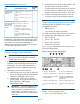
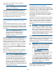

Table 2 Validation tests (continued)
Successful?
(Y/N)Command(s) to executeTest
ping <domain controller
address>
ping <domain controller
name>
Ping the domain
controller from
Node 2.
ping <domain controller
fqdn>
pingpath <domain
controller address>
pingpath <domain
controller name>
Verify the network
path to the domain
controller and
DNS servers is
correct.
pingpath <DNS server
address> (repeat for each DNS
server)
pingpath <DNS server
name> (repeat for each DNS
server)
Additionally, verify that the DNS information is valid
for the cluster and file server. HP recommends that you
also verify the iLO and Enclosure Manager IP
address/name resolution; however, this is not critical
to support the cluster and file server.
Rack the storage system hardware
WARNING! The storage system is heavy.
Always use at least two people to move the
storage system into the rack.
1. If you ordered the storage system without the rack,
install the rail kit and storage system chassis by
following the HP 3U Storage System Rail Kit
Installation Instructions, packaged with the rail
kit.
2. Optionally, install any disk enclosures.
a. Add disk enclosures to the rack by following
the HP 2U Storage System Rail Kit Installation
Instructions, packaged with the rail kit.
b. Cable the disk enclosures to the storage
system chassis. For supported cabling, see
the HP StoreEasy 5000 Storage
Administrator Guide.
IMPORTANT: Ensure that cabling in the
back of the rack does not interfere with
system operation or maintenance. Bind
cables loosely with cable ties and route
excess cable out of the way, along the side
of the rack.
3. Ensure that the disk drives are fully seated in the
disk drive drawer and disk enclosures.
To verify the lever is fully latched, pull on the lever
but do not press the release button. If any lever
appears to be loose, press the lever until it clicks.
4. Connect the storage system power cords to the
rack power supply using standard procedures.
Connect the storage system network cables
The EMU provides connections to two types of
management processors:
• EMU processor
• iLO processor for each server blade
To simplify initial setup, the EMU and iLO processors
are configured for static addressing as follows:
• EMU: 10.0.0.10
• Server 1 iLO: 10.0.0.11
• Server 2 iLO: 10.0.0.12
• Subnet: 255.255.255.0
Figure 3 (page 3) identifies the network ports on the
rear of the storage system.
Figure 3 Storage system network ports
2. Server 2, 10 GbE port 11. Server 1, 10 GbE port 1
4. Server 2, 10 GbE port 23. Server 1, 10 GbE port 2
6. Enclosure Manager NIC
(includes iLO connections for
both servers)
5. Intraconnect (internal switch
connecting EMU)
8. Server 2, Mezz NIC, port 17. Server 1, Mezz NIC, port 1
10. Server 2, PCI-e NIC, ports
1-4
9. Server 1, PCI-e NIC, ports
1-4
Power on the storage system
1. Power on the disk enclosures, if any.
Page 3