HP StoreEver 1/8 G2 Tape Autoloader User and Service Guide Abstract This guide provides information on installing, configuring, upgrading, and troubleshooting the tape autoloader. This guide is intended for system administrators and other users who need physical and functional knowledge of the tape autoloader.
© Copyright 2006, 2012 Hewlett-Packard Development Company, L.P. Hewlett-Packard Company makes no warranty of any kind with regard to this material, including, but not limited to, the implied warranties of merchantability and fitness for a particular purpose. Hewlett-Packard shall not be liable for errors contained herein or for incidental or consequential damages in connection with the furnishing, performance, or use of this material.
Contents 1 Features and overview................................................................................7 Autoloader options...................................................................................................................8 HP StoreEver 1/8 G2 & MSL Encryption Kit............................................................................8 Command View TL TapeAssure..............................................................................................
Using and maintaining tape cartridges.................................................................................30 Labeling tape cartridges.....................................................................................................31 Write-protecting tape cartridges...........................................................................................32 Read and write compatibility...............................................................................................33 Magazines..
Network information (Status/Information > Network Information).........................................72 Configuration....................................................................................................................73 Changing the administrator password (Configuration > Change Admin Password).................73 Setting the number of reserved slots (Configuration > Set Reserved Slot Count)......................74 Configuring the mailslot (Configuration > Configure Mailslot)...............
Error codes..........................................................................................................................104 Finding error code information on the OCP.........................................................................104 Finding error code information on the RMI..........................................................................105 Finding error code information on an L&TT support ticket or report..........................................
1 Features and overview The autoloader provides a compact, high-capacity, low-cost solution for simple, unattended data backup. This unique design houses up to eight tape cartridges in a compact 1U form factor with easy access to tape cartridges via two removable magazines and a configurable mailslot. Each magazine can hold up to four cartridges. The autoloader supports Ultrium half-height tape drives. For the tape drives currently available for the autoloader, see the MSL QuickSpecs at www.hp.com/go/tape.
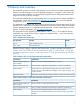
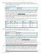
Table 4 Ultrium 6650 1/8 G2 Tape Autoloader specifications Characteristic Specification Maximum storage capacity, 8 data cartridges Native: 20 TB (8 x 2.5 TB) Compressed (2.5:1): 50 TB Maximum data transfer rate Native: 160 MB/s (576 GB/hr) Compressed (2.
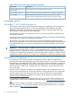
LTFS Automation License Support The HP StoreOpen Automation application extends the Linear Tape File System (LTFS) functionality by presenting an autoloader or library and its tape cartridges as a collection of folders for easy data access and management. For more information about LTFS capabilities, visit the StoreOpen website: http://www.hp.com/go/StoreOpen Enabling the LTFS feature requires a license for the autoloader. Use the RMI Configure: License Key screen to manage the license key.
Interface specifications and requirements for Fibre Channel drives The Fibre Channel tape drive can be connected directly to the server with a host bus adapter (HBA) or through a storage area network (SAN). Table 5 FC drive interface speeds LTO generation Supported speeds LTO-5, LTO-6 2 Gb, 4 Gb, 8 Gb If you plan to connect the autoloader directly to the server, you will need a 2 Gb, 4 Gb, or 8 Gb Fibre Channel HBA. An 8 Gb HBA is recommended for LTO-5 and LTO-6 tape drives for optimal performance.
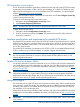
LTO-4 and later generation tape drives and encryption The LTO-4 and later generation tape drives include hardware capable of encrypting data while writing data, and decrypting data when reading. Hardware encryption can be used with or without compression while maintaining the full speed and capacity of the tape drive and media.
IMPORTANT: When encryption is enabled with the encryption kit, the autoloader will not use encryption keys from other sources, such as a key management system or application software. Disable encryption in applications writing to the autoloader when encryption is enabled with the encryption kit. Applications that attempt to control encryption while encryption is enabled with the encryption kit will not be able to do so, which can cause backups or other write operations to fail.
Figure 1 Front panel overview 1. Power button 2. Mailslot 3. Front panel LEDs 4. Front panel LCD screen 5. Control buttons 6. Air vents 7. Magazine The operator control panel includes four LEDs that indicate system status information as shown in “Operator control panel LEDs” (page 13). Figure 2 Operator control panel LEDs 1. Green Ready. Illuminated when power is on. Blinking when there is tape drive or robotics activity. 2. Amber Clean.
7. Serial port (Factory use only) 8. Controller health status indicator 9. USB port Tape drive back panel overviews Figure 4 LTO-5 Fibre Channel back panel Figure 5 LTO-6 Fibre Channel tape drive back panel 1. Magazine release hole 2. Fan 3. Fibre Channel ports. Port A is above; Port B is below. 4. Tape drive power indicator 5. Tape drive Ethernet port Figure 6 SAS tape drive back panel 1. Magazine release hole 2. SAS port. The LTO-4 and LTO-5 drives have one port; the LTO-6 drive has two ports.
Tape drive power indicator Each tape drive has a green power indicator LED, which indicates that the tape drive is powered on (see “Tape drive power indicator” (page 15)). Figure 8 Tape drive power indicator 1. Tape drive power indicator Controller health status indicator The controller health status indicator is a green LED that pulses on and off in approximately one second cycles during normal operation.
2 Installing the autoloader This chapter contains the information you need to install and configure your autoloader.
• Install application software and compatible drivers on the host computer. See the application software manuals for installation and configuration information. • For parallel SCSI autoloaders, make sure multiple LUN support is enabled on the HBA and operating system. See “Multiple LUN support” (page 9). Planning the parallel SCSI configuration If the host computer will have multiple parallel SCSI devices, you must decide how they will be configured into one or more parallel SCSI busses.
Planning the SAS configuration The key steps in planning the SAS configuration are obtaining a suitable HBA and cable. The autoloader uses two SCSI logical unit numbers (LUNs) and requires an HBA with multiple LUN support. Most HP SAS RAID controllers support tape libraries; many non-HP SAS RAID controllers to not support tape libraries. To verify the specifications of your HBA or find a list of compatible HBAs, review the compatibility matrix on the Enterprise Backup Solutions website at: http:// www.hp.
SAS signal rates require clean connections and a minimum number of connections between the HBA and the device. Do not use adapters or converters between the HBA and the device. HP recommends a maximum SAS cable length of six meters. CAUTION: High quality SAS cables rated at the transfer rate of the SAS components are required. Always verify that the SAS cable you are using is rated for the data transfer speed of the interface of your components.
Table 8 Location criteria (continued) Criteria Definition Do not place the autoloader on its sides or upside down. Do not put anything on top of the autoloader unless the optional tabletop conversion cover is installed. The tabletop conversion cover can support up to 15 kg (33 lb). Rack requirements HP Intelligent Series, HP 5000, HP 10000 Series, HP Rack System/E racks.
Figure 11 Product components 1. Autoloader 2. Parallel SCSI or SAS interface cable (parallel SCSI and SAS autoloaders only) 3. Power cord 4. Product documentation 5. Ethernet cable 6. Six support feet 7. SCSI terminator (parallel SCSI autoloaders only) Table 9 Maximum FC cable lengths (in meters) Drive Cable type 2 Gb 4 Gb 8 Gb All OM2 0.5 - 300 m 0.5 - 150 m NA LTO-5 HH* OM3, OM4 0.5 - 300 m 0.5 - 150 m 0.5 - 50 m All except LTO-5 HH OM3, OM4 0.5 - 300 m 0.5 - 380 m 0.
3. 4. 5. 6. Locate the six inscribed foot location lines on the bottom of the autoloader. If the autoloader is not new, clean the foot locations with a damp paper towel. Peel the backing paper off each foot and apply it within a set of foot location lines (see “Attaching the feet to the bottom of the autoloader” (page 22)). With another person, gently turn the autoloader over and set it on its feet.
3. Store the lock on the back panel of the device (see Figure 14 (page 23)). Figure 14 Shipping lock storage location Mounting the device in a rack If you plan to set the autoloader on a table or rack shelf, skip this step and continue with “Installing the Tabletop Conversion Kit” (page 24). WARNING! The autoloader weighs 11.5 kg (25.4 lb) without media and 13.1 kg (28.9 lb) with media (8 cartridges).
2. Secure the front of one rail to the front of the rack. Extend the rail to the depth of the rack and secure the rail to the back of the rack. The front of the rails are straight and the back are angled, as shown in “Installing the rails into the rack” (page 24). Figure 16 Installing the rails into the rack To install the device on the rails and into the rack: 1. Locate the captive screws on the front bezel (see “Securing the autoloader to the rack” (page 24)). 2. Slide the device onto the rails. 3.
Figure 18 Installing the tabletop conversion cover 3. Tighten the captive screws on the front panel until the cover is secure. Changing the SCSI address (parallel SCSI drives only) If you have multiple parallel SCSI devices on the SCSI bus and another device is already using SCSI ID 4, you must change the SCSI ID of the autoloader. To change the SCSI ID: 1. Plug the power cord into the power connector on the back panel and then plug the cord into the power outlet. 2.
3. Attach the other end of the parallel SCSI cable to the connector on the parallel SCSI host bus adapter or to the connector on the previous device on the parallel SCSI bus. NOTE: The host bus adapter should be Low Voltage Differential Signaling (LVDS). A Single-Ended (SE) SCSI host bus adapter works, but severely degrades performance and limits cable length.
Figure 20 Attaching the power cord 3. 4. 5. 6. 7. Plug the power cable into the nearest properly grounded power outlet. Power on the device by pressing the power button located on the front panel. Check the LCD screen to make sure it has power. If not, check the power connections and your power source. During the Power On Self Test (POST), all four LEDs are illuminated briefly, followed by a flashing Ready LED. When the initialization sequence is complete, the Home screen is displayed.
2. Verify the connection between the autoloader and the host: • Install the HP Library & Tape Tools Diagnostic/Installation Check Utility onto the host computer. This utility verifies that the unit is connected and communicating with the host server. It also verifies that the device is functioning and provides diagnostic information. Run the HP Library & Tape Tools Installation Check from the programs menu to verify your connections. L&TT is available without cost at www.hp.com/support/TapeTools.
autoloader configuration is helpful when recovering from a configuration error, setting up multiple devices with similar configurations, or if the autoloader needs service. See “Saving and restoring the device configuration and restoring factory defaults” (page 58). Configuring additional features The autoloader has many features to customize it for your organization. • Enabling and configuring SNMP network management or Command View TL TapeAssure. See “Configuration: Network Management” (page 53).
3 Tape cartridges and magazines This chapter explains which media to use with your autoloader, and how to label and write-protect your tape cartridges. Careful labeling and handling of the tape cartridges will prolong the life of the tape cartridges and the tape autoloader. Tape cartridges Use the Ultrium data and cleaning tape cartridges designed for your model of tape autoloader. You can order data and cleaning cartridges at www.hp.com/go/storagemedia.
• Do not drop a cartridge. Excessive shock can damage the internal contents of the cartridge or the cartridge case itself, making the cartridge unusable. • Do not expose data cartridges to direct sunlight or sources of heat, including portable heaters and heating ducts. • The operating temperature range for data cartridges is 10 to 35º C. The storage temperature range is -40 to +60º C in a dust-free environment in which relative humidity is always between 20 percent and 80 percent (non-condensing).
IMPORTANT: Misusing and misunderstanding bar code technology can result in backup and restore failures. To ensure that your bar code labels meet HP's quality standards, always purchase them from an approved supplier and never print bar code labels yourself. To order bar code labels from an HP-authorized reseller: • In the United States, call 1-800-345-1518. • Elsewhere, see the HP website: www.hp.com, then click Contact HP to find locations and telephone numbers.
Figure 22 Write-protecting the data cartridge 1. Write-enabled 2. Write-protected 3. Write-protect switch 4. Bar code label 5. Insertion arrow Read and write compatibility HP Ultrium data cartridges are fully supported and compatible with HP Ultrium tape products (see “Backward read compatibility” (page 33)). Because HP Ultrium media is Ultrium logo compliant, it may be used with any other non-HP device that bears the Ultrium logo.
Magazines The device has removable magazines. Magazine access is password protected. For safety reasons, the robotic motion is stopped when a magazine is removed. The magazines can be released using the operator control panel (OCP), the remote management interface (RMI), or by a manual release. HP recommends that you release the magazine using the OCP or RMI. The magazine must only be removed manually when the OCP or RMI process has failed, or the device no longer has power.
4 Operating the tape autoloader The tape autoloader can be operated by the following methods: • Remote management interface (RMI) — this interface lets you monitor and control the autoloader from a web page. You can access most autoloader functions from the RMI. • Operator control panel (OCP) — this interface lets you operate the device from the front panel. • Host backup software — You can perform any functions provided by the backup software.
• • ◦ “Changing the administrative password” (page 55) ◦ “Setting date/time” (page 56) ◦ “Setting error log mode” (page 57) ◦ “Setting event notification parameters” (page 57) ◦ “Saving and restoring the device configuration and restoring factory defaults” (page 58) “Operations” (page 59) ◦ “Moving media” (page 59) ◦ “Updating the current media inventory” (page 60) ◦ “Releasing and replacing the magazines” (page 60) “Support” (page 61) ◦ “Performing general diagnostics” (page 61) ◦ “S
Figure 25 RMI login page The Account Types are: • User — no password is required (leave the password box blank). • Administrator — the administrator password is required. The same administrator password is used for the RMI and OCP. There is not a default administrator password; the administrator password must be set with the OCP before it can be used with the RMI. If the administrator password is lost, contact HP to generate a temporary password that will grant administrator access.
• Updated — the day, date, and time of the most recent status view. This timestamp comes from your computer and may be different from the autoloader Time at the bottom of the pane. Click your browser's reload button to refresh the system status. • Status of the autoloader and tape drive The green Status Ok icon indicates that the device is fully operational and that no user intervention is required.
Figure 28 Identity: Autoloader page You can see, but not modify, the following: • Serial Number — the electronic serial number for the device. It should match the serial number printed on the device's label, located on the pull out tab under the drive on the back of the device. • Product ID — how the device identifies itself to the host computer. • Currently Installed Autoloader Firmware x.xx / y.yy ◦ x.xx is the version of the autoloader controller firmware ◦ y.
CAUTION: Since loop mode will endlessly cycle through the tapes, it is possible to overwrite old data. Make sure that there are enough tapes in the autoloader or that the tapes are regularly rotated in and out to ensure that data you want to save is not overwritten. ◦ • Autoload — the device will automatically load the tape from the lowest numbered full slot on power up.
Figure 30 Identity: Drive page (parallel SCSI) Figure 31 Identity: Drive page (SAS) You can see, but not modify, the following: • Vendor ID — will always be HP. • Product ID — product identification information that is given by the drive. • Serial Number — electronic serial number of the drive. It should match the physical serial number of the drive. • Firmware Revision — version of the currently installed drive firmware. • SCSI ID (parallel SCSI drive only) — SCSI address of the drive.
• Autoloader LUN Hosted by Drive — Yes, if this drive is hosting the autoloader at LUN 1. Will always be Yes for the 1/8 G2 Tape Autoloader. • Data Compression — Yes, if the host has hardware compression turned on for the drive. • Interface Type — SCSI, Fibre Channel, or SAS • WWide Node Name (FC drive only) — world wide unique number for the drive. The autoloader assigns WWNames to the drive bays. When a tape drive is replaced, the WWName is re-assigned to the replacement drive.
• IPv4 DNS Server 1 and IPv4 DNS Server 2 — addresses of the configured DNS servers used when DHCP Addressing is not Enabled. • DHCPv4 Addressing — When Enabled, the device will request an IP address from a DHCP server each time the device is booted. • IPv4 Address — the autoloader network address • Subnet Mask — The network mask of the autoloader controller used when DHCP Addressing is not Enabled. • Default Gateway — the gateway used when DHCP Addressing is not Enabled.
• Status — the overall status of the device The device is fully operational and no user interaction is required. User attention is necessary, but the device can still perform most operations. User intervention is required and the device is not capable of performing some operations. • Cartridge in Transport — the slot number where the tape currently in the robot originated. None if there is not a tape in the robotic. • Odometer — the total number of moves the device has performed since its manufacture.
Figure 35 Status: Drive page (FC) Figure 36 Status: Drive page (SAS) You can see, but not modify, the following: Remote management interface (RMI) 45
• Status of the drive The drive is operating normally. The device is functional, but might have an issue that should be addressed. The drive is in a failed state. • Cartridge in Drive — information about the cartridge, if any, currently in the drive. • Drive Error Code — the current drive error code if the drive is in a failed state. See Drive error codes (page 120) for a list of drive error codes. • Internal Drive Temperature — internal temperature reported by the drive.
Figure 37 Status: Inventory page A dark rectangle indicates a full slot, a red rectangle indicates a cartridge with a problem, and a white rectangle indicates an empty slot. To see detailed information about the tapes in a magazine, click on the + button to expand the display for the magazine (see Status:Inventory: Media details pane).
change. In some cases a pop-up screen asks you to confirm the change. Many changes also require the device to reboot. You may need to click Refresh to see the changes. Figure 39 Configuration: System page • Mailslot Configuration Enabled — configures the first slot as a mailslot or storage slot. Enabling the mailslot will reduce the total number of storage slots. The default is disabled.
NOTE: Barcode labels longer than eight characters might scan incorrectly, especially if they are not high-quality labels. • Barcode Label Alignment Reported to Host — configures the end of the bar code label characters to report to the host application when reporting fewer than the maximum number of characters. For example, when reporting only six characters of the bar code label 12345678, if alignment is left, the device will report 123456. If alignment is right, the device will report 345678.
After configuring Autoload mode, you must do one of the following for Autoload mode to take effect: ◦ – Power cycle the device from the front panel. – Reboot the device from the RMI Support: Reboot screen. – Move the lowest-numbered cartridge to the drive before starting the backup application. If the mailslot is enabled, the lowest cartridge location will be in the mailslot.
Figure 41 Configuration: Drive page (Fibre Channel) • Speed — Automatic, 1 Gb/s, 2 Gb/s, 4 Gb/s, or 8 Gb/s. Only speeds supported by the drive are listed. The default is Automatic. • Port Type — Automatic, Fabric (N), or Loop (NL). Direct connected devices are typically Loop. Devices connected to a switch are typically Fabric. The default is Automatic. • Addressing Mode — addressing mode when the port type is Loop: Hard, Soft, or Hard auto-select.
Figure 43 Configuration: Network page You may change the: 52 • Protocol version — selects the Internet Protocols that will be enabled. Select IPv4 only, IPv6 only, or both IPv4 and IPv6 protocols. The default is the IPv4 protocol only. • Host Name — enter the host name provided by your network administrator for the autoloader. • Domain name — enter the domain name provided by your network administrator for the autoloader.
For IPv4, you may change the: • DHCP Address — when On, the autoloader will request an IP address from a DHCP server each time the device is booted. The default is On. • Static Address — configures the IP address if DHCP is not enabled. • Subnet Mask — configures the network mask of the autoloader controller if DHCP Address is not On. • Gateway Address — configures the gateway address if DHCP Address is not On.
Figure 44 Configuration: Network Management page You may change the: 54 • SNMP Enabled — When checked, the device can be managed by computers listed in the SNMP Target IP Addresses field. • SNMP Target IP Addresses — the IP addresses for up to three computers running IPv4 SNMP management software and up to three computers running IPv6 SNMP management software.
• Community Name — a string used to match the SNMP management station and device. It must be set to the same name on both the management station and the autoloader. The default community name is public. • SNMP Trap Notification Filter — the types of events for which the device should send SNMP traps. • IPv4 or IPv6 Management Station — IP address of the Command View TL management station. Only one management station can be configured.
Figure 45 Configuration: Password page You may change the: • Password — The password is exactly eight numbers, each from 0 to 9. • Password Time Out — The number of minutes that the current administrator login session will remain logged in without user interaction. Setting the date and time Use the Configuration: Date/Time page to set the date and time. NOTE: The device does not adjust its time to daylight saving time; the time must be adjusted manually.
• UTC Time Zone Offset — Select the time zone for your area. • Enable Daylight Savings Adjustment — Enabling daylight saving time will advance the local time by one hour. This setting does NOT automatically adjust the device time for daylight saving time based on the calendar. You must manually enable this setting when daylight saving time starts in your area and disable it when daylight saving time ends. Setting error log mode The Configuration: Log page can only be accessed by HP Service personnel.
Saving and restoring the device configuration and restoring factory defaults Use the Configuration: Restore defaults page to restore the factory defaults, reset the administrator password to null, or save the device configuration database to a file. The device will perform an inventory after the defaults are restored. IMPORTANT: Once you reset the administrator password to null, you will not be able to access the administrator functions in the RMI until you set an administrator password through the OCP.
• SNMP: disabled, but saved addresses do not change • E-mail notification: disabled, but configurations retained The following settings are not reset: • Administrator password • Network settings (network is always enabled and the network addresses are retained) • Date and time To save the device configuration to a file, click Save and follow the instructions on the RMI to specify a file location.
Figure 50 Operations: Move Media page To move a tape, select the source and destination and then click the Move button in the center of the screen to start the move. Updating the current media inventory Use the Operations: Inventory page to have the device re-scan the tapes to update the media inventory. Figure 51 Operations: Inventory page Releasing and replacing the magazines Use the Operations: Magazine page to release the left, right, or both magazines.
Support CAUTION: Some RMI operations take the device offline. This inactive mode can interfere with host-based application software, causing data loss. Ensure that the device is idle before attempting to perform any remote operations that take it offline. Performing general diagnostics Use the Support: General Diagnostic page to run general tests to verify the usability and reliability of the device. Select the test and enter the number of test cycles before starting the test.
Determining and updating firmware Use the Support: Firmware page to see the current version of the device and drive firmware, and upload new firmware. The firmware files must be in the HP L&TT format with the .frm file extension. You can find firmware files on the HP Support website: www.hp.com/support. After the firmware is updated, the device or tape drive with updated firmware is reset. CAUTION: Do not interrupt the device while a firmware update is in progress.
Figure 56 Support: Reboot page Viewing logs From the Support: Autoloader Logs page you can see the device logs. The available logs are: Error Trace, Informational Trace, Warning Trace, Configuration Change Trace, and Standard Trace. The log entries are displayed in order of most recent to oldest. The format for the log entries is: YY.MM.DD HH.MM.SS.ss LIB/ERR<80 89 62 40 • YY.MM.DD — the date displayed as Year.Month.Day • HH.MM.SS.ss — the time displayed as Hour.Minute.Second.
Cleaning the tape drive Use the Support: Clean Drive page to clean the tape drive. • Slot # — select the slot number of the cleaning tape Figure 58 Support: Clean Drive page Downloading a support ticket Use the Support: Support ticket page to download a support ticket for the autoloader or tape drive. The support ticket can help a service engineer or system administrator diagnose a device problem. NOTE: LTO 2 and 3 tape drives must be empty to download support tickets.
Operator control panel (OCP) The OCP on the front of the device includes a 2-line by 16-character green backlit liquid crystal display (LCD), four function keys, and four LEDs. This panel provides everything you need to monitor the device status and control its functions.
• ◦ “Rebooting the autoloader (Operations> Reboot Autoloader)” (page 82) ◦ “Enabling password locks (Operations > Enable Autoldr Password Locks)” (page 82) “Support” (page 82) ◦ “Powering a drive on or off (Support > Power On/Off Drive)” (page 82) ◦ “Running the demonstration (Support > Run Demo)” (page 83) ◦ “Running the slot to slot test (Support > Run Slot To Slot Test)” (page 83) ◦ “Running the wellness test (Support > Run Wellness Test)” (page 83) ◦ “Upgrading firmware (Support > Autoloa
Figure 61 Home screen Drive status definitions are listed in Table 14 (page 67).
Figure 62 Operator control panel buttons Cancel Cancels the current menu option, returns to the previous menu level, or returns to the Home screen. Enter Enters the menu or selects the option displayed on the LCD screen. Previous Selects the previous item or value in the currently displayed menu. Next Selects the next item or value in the currently displayed menu.
Figure 63 Autoloader menu tree The administrator password accesses all of the available functionality, except for the HP Service Area. A user without the administrator password has access to the Unlock Mailslot and Status/Information menus. Entering the administrator password TIP: By default, the administrator password is unset; all of the digits are null.
Unlocking the mailslot (Unlock Mailslot) The mailslot in the left magazine is used only with host system software that supports this feature. The mailslot feature allows you to insert or remove a single tape without removing the entire magazine. The benefit of using a mailslot is that the device will not inventory the rest of the slots in the magazine so the device can return to service sooner. The mailslot is in the left magazine.
• Mailslot • Left magazine • Right magazine • Drive Each location provides different information: • Drive or Mailslot: The screen display may read Mailslot AESO32L3, where AESO32L3 is an example of the bar code number on the tape, or it may read Full or Empty. • Left or right magazine: The screen display may read Left Magazine or Right Magazine. The second line on the display indicates which slots have a tape or are empty.
2. Press Previous or Next until the screen displays Autoloader Information. Press Enter to select. By using Previous or Next, you can select from the following information screens: • Autoloader Time • Firmware rev. • Product ID • Serial number • SCSI ID and LUN (SCSI devices only) • Slots and Mailslots • Odometer • Power On Time Drive information (Status/Information > Drive Information) To obtain drive information: 1.
2. 3. 4. Press Previous or Next until the screen displays Network Information. Press Enter to select. Press Previous or Next to access the following information: • IPv4 Network Enabled or Disabled • IPv6 Network Enabled or Disabled • Host Name • Domain Name • MAC Address For IPv4 Network or IPv6 Network, press Enter and then use Previous or Next to access the network addresses and configuration.
4. The screen displays the second number flashing. Repeat Step 3 until you have entered all eight characters. Press Enter to select. After the last number has been entered, the password has been set to the new password. NOTE: If you forget the administrator password, you cannot enter a new password. You must call your customer service representative.
5. The screen displays either Alignment Left or Alignment Right. Use Previous or Next to toggle between the two choices. Press Enter to select the correct alignment. Changing the SCSI address — parallel SCSI devices (Configuration> Change Drive) CAUTION: If you change the SCSI ID, you might need to cycle power on the host server and reconfigure your backup software before you can use the device. This option changes the SCSI address of the tape drive. The tape drive uses logical unit number (LUN) 0.
CAUTION: Use caution when choosing Loop mode because it makes it possible to overwrite data on previously written cartridges. Automatic mode: In Automatic mode, the device switches from Sequential mode into Random mode when it receives certain SCSI commands. Automatic mode is the default setting. To set a behavior mode: 1. From the Home screen, press Previous or Next until the screen displays Configuration. Press Enter to select. 2. Press Previous or Next until the screen displays Autoloader Behavior.
To configure IPv4 network settings: 1. From the Home screen, press Previous or Next until the screen displays Configuration. Press Enter to select. 2. Press Previous or Next until the screen displays Configure Network Settings. Press Enter to select. 3. Press Previous or Next until the screen displays IPv4 Networking Enabled. Press Enter to select. 4. Press Previous or Next until the screen displays DHCP Enabled. To change the setting, press Enter. Press Next until the screen shows the desired setting.
Auto cleaning is disabled by default. You can enable automatic cleaning even if there are no cleaning cartridges in the device. In this case, the device will display a warning message. CAUTION: both. Only enable automatic cleaning in either the backup application or the device, not To configure automatic cleaning: 1. From the Home screen, press Previous or Next until the screen displays Configuration. Press Enter to select. 2. Press Previous or Next until the screen displays Configure Auto Cleaning.
This feature is also useful when installing multiple devices. Either save the configuration before configuring the network or ensure that only one device with the same network configuration is on the network at a time until they have unique network identities. To save the device configuration settings to a USB flash drive: 1. Insert the USB flash drive in the USB port on the back of the device. 2. From the Home screen, press Previous or Next until the screen displays Configuration. Press Enter to select. 3.
3. 4. 5. 6. 7. 8. Press Previous or Next until the screen displays either Unlock Left Magazine or Unlock Right Magazine. Press Enter to select the desired magazine to unlock. Enter the administrator password if requested. The display reads Left Magazine Unlocked or Right Magazine Unlocked. Pull the released magazine out of the device. The screen now displays Insert Left Magazine or Insert Right Magazine. The device cannot perform any other operation until the magazine is replaced.
Moving tapes in the Autoloader (Operations > Move Tape) Use this option to move a cartridge from a tape drive, a tape slot in any magazine or the mailslot to any other location not already holding a tape. You can also load and unload tape cartridges to and from the installed tape drives. You must first select where you want to move the tape from and then indicate where you want to move the tape to. Access to this command requires the administrator password. To move a tape: 1.
NOTE: This command is only needed if the inventory in the device is different than the inventory displayed on the front panel, which would not happen under normal conditions. Rebooting the autoloader (Operations> Reboot Autoloader) This option reboots the device and forces a new cartridge inventory, clearing any current error condition. CAUTION: This option interrupts the current backup or restore operation and causes the operation to fail. Use this option if the device is in an error state. To reboot: 1.
3. 4. 5. Enter the administrator password, if prompted. The screen displays Drive. The second line in the display displays the current state, which is either Power ON or Power OFF. To change the power status, press Enter. The screen displays either Press Enter to Power off Drive, or Press Enter to Power on Drive. Press Enter to select. The Ready LED blinks during the operations. Running the demonstration (Support > Run Demo) Use this option to run a device demonstration program.
For complete testing, enable the mailslot and ensure that each top-row corner slot contains a tape cartridge. During the test, the device will open the mailslot and ask you to insert a tape cartridge. You can use any compatible Ultrium data tape cartridge for this test. IMPORTANT: The device will remove any tape cartridges from tape drives and go offline when running the wellness test. Verify that any applications using the device have completed before starting the wellness test.
1. Download current tape drive firmware using HP Library & Tape Tools or from the HP support website: www.hp.com/support/storage. Copy the firmware onto the USB flash drive. TIP: The display will only show the first 16 characters of the file name. If the USB drive has multiple firmware files, ensure that you can distinguish the files from the first 16 characters in their file names. 2. 3. 4. 5. 6. 7. 8. 9. To 1. 2. 3. 4. 5. 6. 7. 8. 9.
Downloading a support ticket (Support > Download Support Ticket) A support ticket contains information that can help a system administrator or support engineer diagnose device problems. Use this option to download a support ticket to a USB flash drive. Downloading the support ticket to a USB flash drive lets you view the ticket on a computer that is not connected to the device. You can view the support ticket with the Library & Tape Tools. To download a support ticket: 1.
5 Troubleshooting CAUTION: This autoloader is designed to operate with both side edges properly supported. The installation approaches that provide the proper edge support are: • Installed in a rack using the optional Rack Kit. • Installed in the optional Rack-to-Tabletop Conversion Kit sitting on a flat surface. • Sitting on a level surface on the included plastic feet. Operating the autoloader without one of these kits or the feet could result in autoloader errors.
pins. The length of the internal parallel SCSI cabling inside the device is 0.5 m (1.6 ft). This length must be included in any calculations of cable length. • – For LVD SCSI, the maximum length with only a single device on the parallel SCSI bus is 25 m (82 ft). – For Ultra 320 or multiple devices on an LVD bus, the maximum combined internal/external length is 12 m (40 ft).
NOTE: The host bus adapter should be SCSI-3 LVDS. A single-ended parallel SCSI host bus adapter severely degrades performance. Also, if any SE devices are on the same parallel SCSI bus, all of the devices on the bus slow down to SE speed, which severely degrades performance. The autoloader is NOT compatible with a standard differential (Diff) or high-voltage differential (HVD) SCSI bus. • Verify that your HBA is supported by the host computer and qualified with the autoloader.
• ◦ Verify that your HBA is supported by the host computer and qualified with the autoloader. For current HBA compatibility information, see the EBS compatibility matrix at http:// www.hp.com/go/ebs. ◦ Verify that your HBA has the latest firmware. If the application software or operating system detects the tape drive, but not the autoloader: ◦ Verify that multiple LUN support is enabled on the HBA. The device uses two Logical Unit Numbers (LUNs) to control the tape drive (LUN 0) and robotic (LUN 1).
If the screen shows Logged Out: • Check that the Fibre speed is set to Automatic (on the RMI) or Auto Detect (on the OCP), or that the correct fibre speed is selected. If you are unsure of the speed of the HBA or switch that the is connected to, try Automatic (on the RMI) or Auto Detect (on the OCP). • Check that the correct port type, fabric or loop, is selected. Loop requires additional configuration. If you are unsure of the correct port type, try Automatic (on the RMI) or Auto Detect (on the OCP).
Table 17 Failure/attention indications displayed on the front panel Problem Solution “!” in operator panel inventory display. Export the data cartridge marked with an ! in the inventory. The cartridge is either damaged, incompatible with the drive, or the wrong type for the attempted operation. See “Moving tapes in the Autoloader (Operations > Move Tape)” (page 81) for more information. The LCD displays an error code.
Table 19 Media problems Problem Solution Cleaning or data cartridge incompatible with drive. Make sure you are using data and cleaning cartridges that are compatible with the drive and model of your device (see “Tape cartridges” (page 30)) and that you are using the correct cartridge type for the operation. The device automatically unloads incompatible cartridges, the Attention LED flashes, and an exclamation point (!) displays in the inventory display for the indicated slot number.
Table 20 Parallel SCSI device not detected Problem Solution Device not detected • Check that the HBA supports multiple LUNs and this feature is enabled. If not, only the tape drive will be detected. • Check for conflicting SCSI IDs. • Power on the device before powering on the host computer. • Make sure the autoloader does not have the drive off line and that the autoloader is not running a test. • Attach the device to an LVDS SCSI host adapter/bus. • The parallel SCSI cable length might be too long.
Table 21 Attention LED is lit (continued) Problem Solution The Attention LED is lit but the The autoloader was unable to complete the requested operation with the selected Cleaning LED is not lit after a cartridge tape cartridge. load. • Use only cartridges that are compatible with the drive type (see “Tape cartridges” (page 30)). • Use the correct type of cartridges for the operation. For example, use a cleaning cartridge for cleaning.
Table 22 Inventory problems Problem Solution The inventory labels the cartridge Full • Verify that the label is an HP label. The bar code reader might not be able instead of showing its bar code to read other labels. • Verify that the label is properly applied. See “Labeling and loading the tape cartridges” (page 28). • Verify that the label is not soiled. The inventory process takes a long time Apply high-quality HP labels to all tape cartridges.
To find the performance bottlenecks in your system, check the specifications and performance of the: • “Average file size” (page 97) • “File system type” (page 97) • “Connection from the host server to the disks” (page 98) • “Operating system configuration” (page 98) • “Backup server” (page 99) • “Backup type” (page 100) • “Connection from the host server to the device” (page 101) • “Media” (page 102) Average file size The hard drive must seek to the position of a file before it can start re
Table 26 Performance impact of various file systems File system Performance impact Recommendations Disk array GOOD. Disk arrays typically provide excellent access to data. They usually include many disks, which improves bandwidth. None. Server or workstation with RAID VARIABLE.
Figure 65 Removable Storage service 5. 6. Right-click Removable Storage again and select Properties. Change the Startup type to Disabled and click OK. Stop as many programs as possible while a backup or restore is in progress. Be especially aware of monitoring applications, such as anti-virus software, which check every file that is read.
NOTE: Processor speed numbers as based on Intel x86 type processors. Use the equivalent on a RISC or other type of processor. Table 27 Backup server requirements Tape drive Minimum RAM/drive Processor power/drive LTO-5, LTO-6 2 GB 4 GHz In addition to having enough RAM and processing power, ensure that the PCIe bus is at least 64 bit, has a speed of 66 MHz or better, and is not overloaded by too many high-bandwidth cards. PCIe is preferred.
Database backup Performance impact: VARIABLE. To improve performance when backing up data from a database: • Use specific backup agents for the database. • Use the latest versions of the databases. • Do not backup individual mailboxes. • Do not backup specific records or do a record-by-record backup. • Do not backup when the database is in heavy use.
Table 29 SAS HBA speeds required for optimal performance LTO generation HBA speed LTO-4, LTO-5 3 Gb or 6 Gb SAS LTO-6 6 Gb SAS Media Once the data gets to the tape drive, it must be written onto the tape. If there are no bottlenecks and the autoloader starts having performance problems: • Try a new cartridge. A marginal cartridge can cause performance problems when the tape drive has to retry writing to bad spots on the tape. • Clean the tape drive. See “Tape cartridges” (page 30) for instructions.
IMPORTANT: the device. 4. 5. Do not force the pin once you encounter resistance. Doing so can damage Repeat step 3 for the other magazine if necessary. If other tapes are still in the device, or if you were unable to manually remove the magazines and drive, contact HP customer service for further instructions. See “HP technical support” (page 137).
11. The device displays the test completion status, including any recoveries or errors that may have occurred. Error codes If an error occurs during operation, the device stops the current operation and displays an error code on the LCD screen. Unless otherwise noted in “Operation problems” (page 91), record the error code or error message from the LCD screen, and then try to resolve the error by cycling power to the device and retrying the operation.
If you press Next again, the OCP will display the date and time in the format: YYYY-MM-DD followed by the time in 24–hour clock format, where 1:00 pm is 13:00, as shown in Figure 72 (page 105). Figure 72 Date and time in the OCP error log Finding error code information on the RMI You can find error codes on the RMI “Support: Autoloader Logs page” (page 105). The available logs are: Error Trace, Informational Trace, Warning Trace, Configuration Change Trace, and Standard Trace.
is easier to read, but must be generated and read on the host computer. The support ticket can be downloaded from the device and then viewed on any computer with L&TT installed. To generate and view a report or support ticket from L&TT: 1. In the L&TT By Product or By Connection tab, select the device from the device list. 2. Click the Health button on the main toolbar to generate and display a standard report.
• Events in the last 24 hours • Events in the last 31 days • Events older than 31 days Set the Current Detail Level to see additional types of events: • Normal will only show critical events or hard errors. • More details will also show warning and configuration events. • Everything shows all events. Critical events are designated with a STOP sign icon. Expand the event for more information, as shown in Figure 75 (page 107).
Main error code descriptions Table 30 Main error codes Error code Description Details and solution 80 Cannot initialize bar code reader Power-cycle the unit and retry the operation. 81 No response from bar code reader • Power-cycle the unit and retry the operation. • Update the firmware to the latest version. 82 No response from EEPROM on robotic controller Power-cycle the unit and retry the operation.
Table 30 Main error codes (continued) Error code 89 Description 1 Gripper obstructed Details and solution • Ensure that nothing is obstructing the gripper. • If the device was moved, verify that each of the tape cartridges is properly seated in a magazine. • Run the wellness test. 8A Slider2 obstructed • If this error occurs with subcode 45 and new media, remove the magazine and manually load and unload the new media five times for each new cartridge to condition the new cartridges.
Table 30 Main error codes (continued) Error code Description Details and solution cartridges did not come out of the magazines to obstruct the robotic. • Ensure that nothing is stacked on top of the device because any weight on top of the device can bow the top cover down and interfere with the robotics. If the autoloader has a tabletop conversion cover, verify that no more than 15 kg (33 lb) is on top of the cover.
Table 30 Main error codes (continued) Error code Description Details and solution 3 95 Elevator reached a position beyond expected range 96 Rotation4 reached a position beyond expected range 97 Sled5 reached a position beyond expected range 98 Cartridge present sensor not found 2 99 Slider home sensor not found 9A Rotation4 home sensor not found 9B Sled5 position sensor not found • Power cycle the device and retry the operation. • Power cycle the device and retry the operation.
Table 30 Main error codes (continued) Error code 9F Description 4 Rotation range of motion out of specification Details and solution • Remove all magazines and look for any obstructions to the robot. • Run the wellness test. A0 Sled5 range of motion out of specification • Remove all magazines and look for any obstructions to the robot. • Run the wellness test. A1 Open Mailslot failed • Retry the operation. • Ensure that nothing is obstructing the opening of the mailslot.
Table 30 Main error codes (continued) Error code Description Details and solution operation. C0 Network initialization failed • Check the network cable. • Check that the network configuration is correct. • If DHCP is enabled, ensure that a DHCP server is up an running on the device's network. • Power cycle the device and try again. C1 Telnet interface initialization failed • Check the network cable. C2 Web server initialization failed • Check that the network configuration is correct.
Table 30 Main error codes (continued) Error code D7 Description Details and solution Firmware upgrade error This error can occur is an attempt is made to upgrade a drive with the wrong personality or version for that drive. • Ensure that the correct drive firmware is being used to update the drive. • If the correct drive firmware is being used, update the autoloader firmware. • Power cycle the device and attempt the operation again.
Table 30 Main error codes (continued) Error code DA Description Details and solution When running the wellness test, the bar code did • Check the bar code label for proper not match the previous value for that tape application and damage. • Run the wellness test again. DC I2C Bus failure. • Power-cycle the device. E1 Key server token backup not successful (not enough available space on target token) • Retry the backup with a token with space for more keys. NOTE: Each token can hold 100 keys.
Table 30 Main error codes (continued) Error code Description Details and solution F3 Drive hardware error • Cycle power, after several occurrences, contact technical support. F4 Load time-out. The drive has run into a time-out while loading a tape. • Check that the tape cartridge is supported and has not exceeded its usage life. Inspect it for damage. • Retry the operation. • Clean the drive. • If the issue continues, remove the drive and inspect the opening for any obstructions.
5 Sled: The part of the robotics assembly that moves the robot towards the OCP or back towards the drive.
Table 31 Robotic error sub-codes (continued) Sub-code 118 Description 31 Error during sled5 movement in FLMoveRotation 32 Command sending to robotic failed 33 Error during elevator3 movement in FLMoveRotation function 34 Error during rotation4 in FLMoveRotation function 35 Error during elevator3 movement in FLMoveRotation function 36 Error during sled5 movement in FLMoveSled function 37 Error during sled5 positioning to sensor in FLMoveSled function 38 Error during sled5 positioning to mai
Table 31 Robotic error sub-codes (continued) Sub-code Description 61 Error during first slider2 movement 62 Error during first gripper1 movement 63 Error during second slider2 movement 64 Error during second gripper1 movement, get range failed 65 Error during third slider2 movement, move home failed 70 Release magazine failed 71 Error during sled5 movement to rotation4 position 72 Error during rotation4 to unlock position 73 Error during move sled5 to block 80 Opening mailslot failed 8
Table 31 Robotic error sub-codes (continued) Sub-code Description C2 Elevator3 movement during check on magazine type failed C3 Sled5 movement during check on magazine type failed C4 Sled5 movement to sensor during check on magazine type failed 1 Gripper: The part of the robotics assembly that pinches media in order to grip it. 2 Slider: The part of the robotics assembly that plunges in and out for get and put operations.
Warning events Table 34 Warning event codes Event code Description Details and Solution 30 SCSI: transport element full 31 SCSI: all slots empty 32 SCSI: invalid opcode 33 SCSI: invalid element address 34 SCSI: invalid field in CDB 35 SCSI: invalid drive specified 36 SCSI: SEND DIAGNOSTIC command: invalid test number 37 SCSI: invalid LUN 38 SCSI: parameter list length error 39 SCSI: parameter list error: invalid field 3A SCSI: parameter list error: parameter not supported 3B SCSI:
Table 34 Warning event codes (continued) Event code Description Details and Solution drive has been installed. Use only HP-approved support to insure that the correct tape drives are used. 49 SCSI: incompatible magazine, magazine not accessible Verify that a supported magazine for that slot is inserted. If the magazine is in the lower left position, verify that the type of magazine is consistent with the mailslot configuration. 4A Source not ready • Retry the operation.
Table 34 Warning event codes (continued) Event code Description Details and Solution 5D Wrong drive firmware — invalid drive firmware type. Drive firmware is specific to the drive model and interface. Select the drive firmware specific to this drive. If the firmware file could have been renamed, obtain a new copy of the firmware file 5F No firmware downgrade possible.
Table 34 Warning event codes (continued) Event code Description Details and Solution 7B Invalid firmware version. Only signed firmware images are allowed. The autoloader will only accept signed firmware images. Download a signed firmware image. 80 Movement retry. Robotics movement did not succeed but was successful on a retry. Recovered error move operation. No action required. Occasional retries are normal operation. 81 Drive sled fan alert. Fan motion has stopped.
Table 34 Warning event codes (continued) Event code F2 Description Details and Solution Drive sled missing. • Power cycle the device and retry the operation. • Re-seat the tape drive to ensure a good connection to the device. FF The master drive was removed without being powered off. Library path failover cannot be performed. The master drive must be powered off from the RMI or OCP to activate control path failover.
Table 35 Configuration change events (continued) Value Configuration event Description 0x66 Database has been restored from robot The library configuration has been restored from the robot 0x67 Serial number has been changed The serial number has been changed 0x68 World wide identifier base has been changed The world wide identifier base has been changed 0x69 EUI64 identifier has been changed EUI64 identifier has been changed 0x6E License key has been added or removed License key has been a
Table 36 Informational events (continued) Value Informational event Description 0x19 Restore initiated on key server token A restore operation was initiated on the key server token. 0x1A Restore off key server token finished A restore operation was completed on the key server token. 0x1B Key server token is over 90% full The key server token is over 90% full. 0x1C Key server token contains keys that have not been backed up. The key server token contains keys that have not been backed up.
6 Upgrading and servicing the tape autoloader WARNING! The autoloader weighs 11.5 kg (25.4 lb) without media and 13.1 kg (28.9 lb) with media (8 cartridges).
NOTE: You may use the HP Library and Tape Tools (L&TT) diagnostic utility to perform diagnostic functions for the autoloader. L&TT is a diagnostic tool designed to aid in the installation and maintenance of HP tape storage products. L&TT includes several features designed for use by both HP storage customers and trained service personnel. L&TT is available for download at the following HP website at no cost: www.hp.com/support/TapeTools.
6. Pull straight back on the tape drive handle to remove the tape drive from the autoloader (see Figure 79 (page 130)). Figure 79 Removing the tape drive To replace a tape drive: 1. Before installing the new drive, inspect the connectors on the tape drive. Ensure that the connectors are intact, free of any foreign objects, and have no cracks or deformed or bent contacts. 2.
Removing and replacing a magazine CAUTION: Only remove a magazine manually in an emergency or if you need to remove the magazines from both sides of the device. Failure to follow normal procedure can cause data loss and equipment damage. If possible, the magazines should be released using the OCP or RMI.
Figure 82 Operations: Magazines page Using the manual magazine release 1. From the back of the autoloader determine which magazine needs to be removed using “Manual magazine release holes” (page 132). Figure 83 Manual magazine release holes 2. 1. Right magazine release 2. Left magazine release Push a small metal pin or paper clip about 1.5 cm (0.
• Remove the cables, drives, and magazines from the autoloader. • Remove the autoloader from the rack or tabletop conversion cover. • Replace the base chassis. • Reinstall the autoloader into the rack or tabletop conversion cover if the support feet have not been applied. • Replace the cables, tape drive, and magazines. • Reconfigure the autoloader. ! The autoloader weighs 11.5 kg (25.4 lb) without media and 13.1 kg (28.9 lb) with media (8 cartridges).
2. Pull straight back on the tape drive handle to remove the tape drive from the autoloader (see Figure 86 (page 134)). Figure 86 Removing the tape drive Removing the base chassis You will need a #2 Phillips screwdriver to remove and replace the base chassis assembly from the rack or cover. CAUTION: Lift the autoloader from the side edges. Lifting the autoloader from the magazine or tape drive openings can damage the autoloader. To remove the base chassis from the rack or table top conversion cover: 1.
Replacing the base chassis CAUTION: Lift the chassis from the side edges. Lifting the chassis from the magazine openings can damage the chassis. 1. The shipping lock prevents the robotic transport mechanism from moving during shipment. You must remove the shipping lock before powering on the device. The shipping lock is held in place with a piece of tape and is located in the top center of the new chassis.
Figure 90 Sliding the autoloader into the cover 3. 4. 5. 6. 7. 8. 136 Replace the tape drive. Replace the magazines. Replace the cords and cables. Reconnect the cables and power cord. Power on the autoloader. Reconfigure the autoloader.
7 Support and other resources HP technical support Telephone numbers for worldwide technical support are listed on the HP support website: www.hp.com/support.
Table 37 Document conventions (continued) Convention Element Monospace text • File and directory names • System output • Code • Commands, their arguments, and argument values Monospace, italic text • Code variables • Command variables Monospace, bold text WARNING! CAUTION: IMPORTANT: NOTE: TIP: Emphasized monospace text Indicates that failure to follow directions could result in bodily harm or death. Indicates that failure to follow directions could result in damage to equipment or data.
After registering, you will receive e-mail notification of product enhancements, new driver versions, firmware updates, and other product resources. HP-authorized reseller For the name of your nearest HP-authorized reseller: • In the United States, call 1–800–282–6672 • Elsewhere, visit the HP website: www.hp.com, then click Contact HP to find locations and telephone numbers.
8 Documentation feedback Send any errors, suggestions, or comments to Documentation Feedback (docsfeedback@hp.com).
A Technical specifications Physical specifications Table 39 1/8 G2 tape autoloader physical specifications: all models Characteristics Product alone Packaged Height 44 mm (1.73 inches) 250 mm (9.84 inches) Width 482 mm (18.98 inches) 580 mm (22.83 inches) Depth 809 mm (31.85 inches) 990 mm (38.98 inches) Weight 11.5 kg (25.35 pounds) 25.5 (33.
Table 41 CSA test conditions (continued) Characteristic Tested condition or value Considered current rating (A) 20 A (branch circuit protection) Pollution degree (PD) PD 2 IP protection class IPX0 Altitude during operation (m) Max 2000 Altitude of test laboratory (m) 38 Mass of equipment (kg) Max 25 kg Manufacturer's Declared Ambient (°C) 40 °C NOTE: 142 The CSA test conditions might differ from the product specification limits.
B Regulatory information For important safety, environmental, and regulatory information, see Safety and Compliance Information for Server, Storage, Power, Networking, and Rack Products, available at http:// www.hp.com/support/Safety-Compliance-EnterpriseProducts. Regulatory compliance identification numbers For the purpose of regulatory compliance certifications and identification, this product has been assigned a unique regulatory model number.
C Electrostatic discharge To prevent damaging the system, be aware of the precautions you need to follow when setting up the system or handling parts. A discharge of static electricity from a finger or other conductor may damage system boards or other static-sensitive devices. This type of damage may reduce the life expectancy of the device.
Glossary B barcode reader A component of the robot that is used for cartridge identification and position calibration. C cartridge The plastic housing around a cartridge tape. A plastic leader block is attached to the tape for automatic threading when loaded in transport. The spine of the cartridge contains a label listing the volume identification number. cell The slot in the magazine that is used to store a tape cartridge.
H HBA An acronym for host bus adapter, an interface card which plugs into the computer's bus and connects it to the network. host One or more computers that generate and communicate data to the device. hot-plug, hot swap The plugging in or removal of a drive into a system with the power turned on. HVDS High voltage differential signaling, also called differential SCSI. HVDS supports cable lengths up to 25 meters.
robot An electro-mechanical device that transports tape cartridges to and from the magazines and drives. robotics unit The unit that includes the robotic components and that controls the movement of the robot between storage slots, drives, and load ports. S SAS Serial Attached SCSI. A computer bus technology and serial communication protocol for direct attached storage devices, including disk drives and high-performance tape drives.
Index A administrator password changing OCP, 73 RMI, 55 restoring to null RMI, 58 setting OCP, 73 alerts configuring RMI, 57 Autoloader modes OCP, 75 autoloader modes RMI, 47 automatic cleaning configuring OCP, 77 RMI, 47 B backup application parallel SCSI troubleshooting, 88 SAS troubleshooting, 90 boot straps, using, 144 C cables parallel SCSI, 87 SAS, 89 Command View TL, 8 compatibility parallel SCSI troubleshooting, 88 SAS troubleshooting, 90 configuration settings restoring from file RMI, 58 saving t
configuring RMI, 57 events configuration change, 125 information, 126 warning, 121 F factory defaults restoring OCP, 78 RMI, 58 features, 7 firmware finding version RMI, 62 updating OCP, 84 RMI, 62 floor mats, dissipating, 144 G ground strap specifications, 144 grounding methods, 144 straps, wearing, 144 suggested equipment for, 144 H HBA requirements, 9 heel straps, using, 144 help obtaining, 137 host adapter parallel SCSI troubleshooting, 88 SAS troubleshooting, 90 HP technical support, 137 I installi
termination, 89 parts proper handling, 144 storing, 144 transporting, 144 password default, 37 password locks enabling, 82 preventing electrostatic damage, 144 product specification data storage, 7 data transfer rate, 7 LTO generation, 7 SCSI parallel interface, 7 R rebooting OCP, 82 RMI, 62 regulatory compliance identification numbers, 143 regulatory information, 143 Turkey RoHS material content declaration, 143 Ukraine RoHS material content declaration, 143 remote management interface, 35 repairing remov
parallel SCSI device not detected, 94 performance autoloader connection, 101 backup server, 99 backup type, 100 disk array connection, 98 file size, 97 file system, 97 media, 102 operating system, 98 power, 91 removing stuck tapes, 92 RMI network connection, 96 tape movement, 92 Turkey RoHS material content declaration, 143 U Ukraine RoHS material content declaration, 143 V viewing information autoloader identity OCP, 71 RMI, 38 autoloader status RMI, 43 drive identity OCP, 72 RMI, 40 drive status RMI, 44