HP StoreEver 1U Rack-mount Enclosure User Guide This document provides installation instructions and specifications for the HP StoreEver 1U rack-mount enclosures. It is intended for system administrators and technicians experienced with installing tape drives and other hardware into a rack.
© Copyright 2005, 2013 Hewlett-Packard Development Company, L.P. The information contained herein is subject to change without notice. The only warranties for HP products and services are set forth in the express warranty statements accompanying such products and services. Nothing herein should be construed as constituting an additional warranty. HP shall not be liable for technical or editorial errors or omissions contained herein.
Contents 1 Introduction...............................................................................................4 Standard Features.....................................................................................................................4 Supported Controllers and HBAs................................................................................................4 SAS Cabling Recommendations..................................................................................................
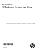
1 Introduction The HP StoreEver 1U Rack-mount Enclosure is a rack-mountable storage system capable of holding up to two half-height 5.25 inch tape or RDX disk drives. It is compatible with most standard 19 inch racks. Figure 1 1U Rack-mount Enclosure Standard Features Standard features of the 1U rack-mount enclosure: • Supports one or two 5.
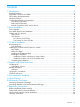
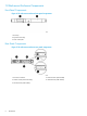
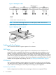
Figure 2 External SAS ports on the 1U rack-mount enclosure When two SAS devices are installed, the right–most connector of the internal cable is connected to the device on the right and the left-most connector of the internal cable is connected to the device on the left. This routes the right-hand device to external port 1 and the left-hand device to external port 2.
1U Rack-mount Enclosure Components Front Panel Components Figure 4 1U rack-mount enclosure front panel components 1. Drive bay 2. Expansion drive bay 3. Power switch/LED Rear Panel Components Figure 5 1U rack-mount enclosure rear panel components 1. AC Power Connector 2. SCSI Connector (SCSI models) 3. SCSI ID Switch (SCSI mode Only) 4. USB Connector (USB models) 5.
Internal Components (SAS version shown) Figure 6 1U rack-mount enclosure internal components (SAS version) 1. Drive 2. Drive blank 3. Power supply 4. Fan assemblies (2) 5.
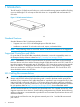
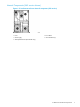
2 Drive Installation Tools Required A 3/16” (5mm) flat-blade screwdriver or T-15 Torx driver may be required to install a drive in the 1U rack-mount enclosure. Drive Blank Removal and Installation CAUTION: To avoid damaging the equipment due to electrostatic discharge, be sure to review and practice the procedures in Electrostatic discharge before handling the drives. To install a tape or disk drive: 1. Remove the top access panel as shown. Figure 7 Removing the access panel 2. Remove the drive blank: a.
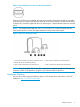
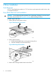
Figure 9 Removing the mounting brackets from the blank 4. Install the mounting brackets to the sides of the drive. Always use the screws provided with the drive. Figure 10 Installing the mounting brackets on the drive CAUTION: When installing an LTO half-height tape drive, it is particularly important that you use the 6 mm M3 screws provided with the drive. If the screws are too long, they may damage the mechanism and void the warranty.
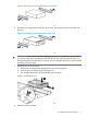
Figure 12 Attaching the cables 1. Power 2. Data 3. SCSI ID selector switch (SCSI drives only) NOTE: 7. Fold excess cable length and secure with the clips provided in the enclosure. Replace the top access panel as shown. Figure 13 Replacing the access panel Cabling with Two Devices The 1U rack-mount enclosure supports operation of two devices. SAS Devices The 1U rack-mount enclosure supports operation of two SAS devices on two SAS buses.
NOTE: One device per SCSI bus is the recommended configuration for LTO–3 and LTO–4 drives. Figure 14 Single-device SCSI configuration 1. Device 1 2. Device 2 3. SCSI bus 1 cable, SCSI connector nearest terminator is 4. SCSI bus 2 cable, SCSI connector nearest terminator is used for device 1 used for device 2 5.
NOTE: Each SCSI device on the same SCSI bus must have a unique SCSI ID. Be sure that the SCSI ID is different for each device and that neither is set to SCSI ID 7, which is reserved for the SCSI controller. NOTE: When adding a second device for configurations using a single SCSI bus. 1. Unplug the SCSI cable from device 1. 2. Pass the end of the cable through internal chassis openings. 3. Plug the end port into device 2. 4. Then plug the middle port into device 1.
3 1U Rack Installation Rail Mounting Kit The rack rails supplied with the 1U rack-mount enclosure can be used to install the unit in racks that have round, square, or threaded holes in the vertical mounting columns. The rails will fit racks with 23 - 34 inches (58 - 86 cm) separation between the front and rear vertical mounting columns. The rails are identical and may be mounted on either the left or the right side. Figure 16 Rail mounting kit components 1. Outer rack rails 2. Inner component rails 3.
When installing the enclosure in a rack: • Start at the bottom of the rack, or at the top of a previously mounted component, and work upward • HP recommends installing the heaviest components at the bottom and lighter ones toward the top of the rack • Make sure that the rack-mounting rails are level from front to back and side to side Before You Begin If you are installing the 1U rack-mount enclosure in a rack with unmarked holes in the vertical mounting columns, identify and mark the correct mounting
1. Insert the pins in front mounting plate of the outer rack rails into the previously marked holes in the front vertical mounting columns of the rack. The rack rails will lock securely into place. Figure 18 Inserting the pins NOTE: To remove the rail for repositioning, push the spring-loaded tab (3) on the outside of the rack rail and slide it forward (4). 2.
1. Remove the pins and threaded plates from both ends of each outer rack rail. These pieces will not be used. Figure 20 Removing the pins and threaded plates NOTE: 2. The ends of the rack rails are marked FRONT and REAR for proper orientation. Attach the front mounting plate of each outer rail to the rack using four 10-32 screws in the previously marked holes in the front vertical mounting columns of the rack.
3. Extend the rack rails past the rear vertical mounting columns and attach the back mounting plate of each outer rail to the rack using four 10-32 screws in the previously marked holes. Figure 22 Attaching the back mounting plate Completing the Installation 1. 2. 3. Ensure all rack safety precautions stated in “Rack Safety” (page 13) have been implemented. Extend the left and right rack rails from the front of the rack.
Figure 24 Connecting the power cord (USB drive installed) 8. Install the cable support clips at the back of the rack rails on one or both sides of the enclosure. Figure 25 Installing the cable support clips 9. 18 Turn on the power to the enclosure with the front panel power button.
4 Support and Other Resources Contacting HP For worldwide technical support information, see the HP support website: http://www.hp.
Table 1 Document conventions (continued) Convention Element Monospace text • File and directory names • System output • Code • Commands, their arguments, and argument values Monospace, italic text • Code variables • Command variables Monospace, bold text WARNING! CAUTION: IMPORTANT: NOTE: TIP: Emphasized monospace text Indicates that failure to follow directions could result in bodily harm or death. Indicates that failure to follow directions could result in damage to equipment or data.
5 Documentation feedback HP is committed to providing documentation that meets your needs. To help us improve the documentation, send any errors, suggestions, or comments to Documentation Feedback (docsfeedback@hp.com). Include the document title and part number, version number, or the URL when submitting your feedback.
A Specifications Specification S.A.E. Metric Height 1.7 in 4.32 cm Depth 25.3 in 64.14 cm Width 19.0 in 42.88 cm Weight (1 drive installed) 20 lb 9.07 kg 90 to 264 VAC 90 to 264 VAC 2.4 A 47 - 63 Hz 2.
B Electrostatic Discharge Preventing Electrostatic Discharge To prevent damaging the system, be aware of the precautions you need to follow when setting up the system or handling parts. A discharge of static electricity from a finger or other conductor may damage system boards or other static-sensitive devices. This type of damage may reduce the life expectancy of the device. To prevent electrostatic damage: • Avoid hand contact by transporting and storing products in static-safe containers.
C Regulatory Information For important safety, environmental, and regulatory information, see Safety and Compliance Information for Server, Storage, Power, Networking, and Rack Products, available at http:// www.hp.com/support/Safety-Compliance-EnterpriseProducts. This document may also be included with the shipped product as a printed document or on a documentation CD/DVD.
HP Enterprise Servers http://www.hp.com/support/EnterpriseServers-Warranties HP Storage Products http://www.hp.com/support/Storage-Warranties HP Networking Products http://www.hp.