HP StoreEver 3U Rack-mount Enclosure User Guide This document provides installation instructions and specifications for the HP StoreEver 3U rack-mount enclosures. It is intended for system administrators and technicians experienced with installing tape drives and other hardware into a rack.
© Copyright 2005, 2013 Hewlett-Packard Development Company, L.P. The information contained herein is subject to change without notice. The only warranties for HP products and services are set forth in the express warranty statements accompanying such products and services. Nothing herein should be construed as constituting an additional warranty. HP shall not be liable for technical or editorial errors or omissions contained herein.
Contents 1 Introduction...............................................................................................4 Standard Features.....................................................................................................................4 Supported Controllers and HBAs................................................................................................4 SAS Cabling Recommendations..................................................................................................
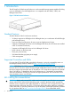
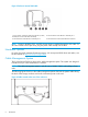
1 Introduction The HP StoreEver 3U Rack-mount Enclosure is a rack-mountable storage system capable of holding up to two full-height or four half-height drives. It is compatible with the 10000, 11000, and Intelligent Series racks.
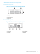
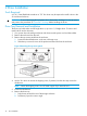
The SAS interface board has two external ports illustrated below. The supplied internal SAS cable supports connection of two devices. Several cabling configurations are possible, but the following cabling configuration is recommended to provide the most consistent layout between devices and external connectors.
Figure 3 Enclosure internal SAS cable 1. and 3. Power connectors (used only with LTO-5, LTO-6, and DAT; do not use with other LTO drives) 4. SAS connector routes device to external port 1 2. SAS connector routes device to external port 2 5. SAS connector to PC board within the enclosure NOTE: Power for all DDS, LTO-5, and LTO–6 tape drives is supplied through the SAS cable. For all earlier models of LTO tape drive, plug the power cable directly into the drive.
3U Rack-mount Enclosure Components Front Panel Components Figure 5 3U rack-mount enclosure front panel components 1. Drive bay 2. Power indicator LED 3. Power switch Rear Panel Components Figure 6 3U rack-mount enclosure rear panel components 1. Power supply 2. Power connector 3. Connectors 4.
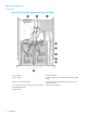
Internal Components SAS Version Figure 7 3U rack-mount enclosure internal components (SAS) 1. Fan assembly 2. SAS interface (2) 3. Power supply 4. Power connector (use with LTO-2, LTO-3 and LTO-4 tape drives) 5. Power switch and LED cables 6. SAS cable and data connector (example shows SAS cable with power) 7. Power connector on SAS cable (use with LTO-5, LTO-6, and all DAT tape drives) 8. Power switch assembly 9.
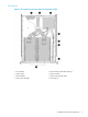
SCSI Version Figure 8 3U rack-mount enclosure internal components (SCSI) 1. Fan assembly 2. Internal LVD/SE Wide SCSI cables (2) 3. Power supply 4. Power connector 5. SCSI terminator 6. Power switch and LED cables 7. Power switch assembly 8.
2 Drive Installation Tools Required A 3/16” (5mm) flat-blade screwdriver or T-15 Torx driver may be required to install a drive in the 3U rack-mount enclosure. CAUTION: To avoid damaging the equipment due to electrostatic discharge, be sure to review and practice the procedures in Electrostatic discharge before handling the drives. Drive Tray Removal and Installation The drive tray holds either one full height drive or, up to two 1/2 height drives. To remove and install a drive into the drive tray: 1.
Figure 10 Removing the empty drive tray 7. Loosen the two fasteners (1) clamping the top bracket on the drive tray. Then unscrew and remove the drive blank(s). Figure 11 Loosening the fasteners 8. To position and align the drive in the drive tray, use the holes labeled A1, A2, or B. After the drive is aligned, secure the drive with retaining screws. With tape drives, always use the screws provided with the tape drive.
11. Place the drive tray in the enclosure at an angle and lay it flat. Then slide it toward the front of the enclosure. NOTE: Make sure that the slots on the drive tray line up with the tabs on the enclosure. Figure 13 Installing the drive tray assembly NOTE: Take care when installing the right-hand drive tray. It should be lowered into position between the front bezel and the baffle that is located behind the power switch.
Figure 14 SAS LTO-5, LTO-6, and all DAT drive cable connections 1. Power connector 2. SAS data cable (with power) SAS LTO–2, LTO–3 and LTO–4 Tape Drive Installation NOTE: These instructions do not apply to LTO-5, LTO-6, or DAT tape drives; see “SAS LTO-5, LTO-6, and all DAT Tape Drive Installation” (page 12). IMPORTANT: High quality SAS cables rated at the transfer rate of the tape drive are required.
SCSI Drive Installation There are four internal SCSI cables; each cable has two SCSI connectors. NOTE: One device per SCSI bus is the recommended configuration for LTO–3 and LTO–4 drives. SCSI IDs The default SCSI ID for each drive depends on the cable configuration used in the storage enclosure. • If there is one drive per SCSI cable, the default is 0. • For two drives per SCSI cable, the default for the top drive is 1 and the default for the bottom drive is 0.
Figure 16 Cabling SCSI devices 1. Internal SCSI cables (2 shown) 2. SCSI terminator 3. SCSI connector (always used) 4. Second SCSI connector (only used if 2 devices per bus, not recommended) Two Devices per SCSI Bus To ensure maximum performance, one device per SCSI bus is the recommended configuration for LTO–3 and LTO–4 drives. If adding a second device for configurations using a single SCSI bus. 1. Unplug the SCSI cable from device 1. 2. Pass the end of the cable through internal chassis openings.
3 3U Rack Installation Rack Mounting Kit The rack mounting kit that ships with the HP StoreEver 3U Rack-mount Enclosure is intended for use with 10000, 11000, and Intelligent Series racks. A template is available on the HP website to mark the rack for proper alignment of rack-mounting brackets. The template is located on the Manuals page of the HP Business Support Center website.
Figure 17 Measuring with the template 3. Repeat steps 1 and 2 on the back of the rack. Installing the Rails and Enclosure To install the rails and enclosure: 1. From the rear of the rack, insert the front tabs of the spring-loaded rack rail into the proper holes. 2. Press the rail forward and insert the rear tabs of the spring-loaded rack rail into the proper holes. The rail locks into place securely. Figure 18 Aligning and inserting the spring-loaded rack rail (rear view) 3. 4.
Figure 19 Attaching the cable management reel 5. 6. Tighten the thumbscrew into the spring-loaded rack rail. From the rear of the rack, align the cable rack bracket with the hole in the left spring-loaded rack rail and secure it with an M6 x 1.0-12L Phillips screw. Figure 20 Attaching the cable rack bracket 7. 8. Tighten the thumbscrew into the spring-loaded rack rail. Align the rear of the storage enclosure rails with the front end of the spring-loaded rack rails, then push it fully into the rack.
Figure 21 Inserting the enclosure into the rack 9. Plug an external data cable from the controller to the data connector on the back of the chassis. 10. Repeat Step 9 for each controller in your system. 11. Plug the AC power cord into the power cord connector. 12. Route the system cables to the cable reel and secure with the Velcro® strip. 13. Route the system cables to the cable rack bracket and secure with the Velcro® strip. Figure 22 Cables routed through cable management assembly 14.
4 Support and Other Resources Contacting HP For worldwide technical support information, see the HP support website: http://www.hp.
Table 1 Document conventions (continued) Convention Element Monospace text • File and directory names • System output • Code • Commands, their arguments, and argument values Monospace, italic text • Code variables • Command variables Monospace, bold text WARNING! CAUTION: IMPORTANT: NOTE: TIP: Emphasized monospace text Indicates that failure to follow directions could result in bodily harm or death. Indicates that failure to follow directions could result in damage to equipment or data.
5 Documentation feedback HP is committed to providing documentation that meets your needs. To help us improve the documentation, send any errors, suggestions, or comments to Documentation Feedback (docsfeedback@hp.com). Include the document title and part number, version number, or the URL when submitting your feedback.
A Specifications Specification S.A.E. Metric Height 5.2 in 13.2 cm Depth 23.0 in 58.4 cm Width 16.8 in 42.7 cm Weight (1 drive installed) 27 lb 12.3 kg 90 to 264 VAC 90 to 264 VAC 3.1 A 47 - 63 Hz 3.
B Electrostatic Discharge Preventing Electrostatic Discharge To prevent damaging the system, be aware of the precautions you need to follow when setting up the system or handling parts. A discharge of static electricity from a finger or other conductor may damage system boards or other static-sensitive devices. This type of damage may reduce the life expectancy of the device. To prevent electrostatic damage: • Avoid hand contact by transporting and storing products in static-safe containers.
C Regulatory Information For important safety, environmental, and regulatory information, see Safety and Compliance Information for Server, Storage, Power, Networking, and Rack Products, available at http:// www.hp.com/support/Safety-Compliance-EnterpriseProducts. This document may also be included with the shipped product as a printed document or on a documentation CD/DVD.
HP Enterprise Servers http://www.hp.com/support/EnterpriseServers-Warranties HP Storage Products http://www.hp.com/support/Storage-Warranties HP Networking Products http://www.hp.