
HP StoreEver Enterprise Systems Library (ESL) G3 Tape Library Controller Hardware Revision 2 Robot Replacement Instructions
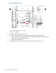
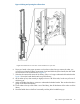
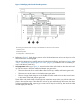
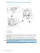
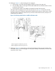
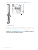

Figure 9 Identifying robot loader bracket positions
The X-axis gear rack has been cut away in this illustration to show the screw locations.
1. Insertion point
2. Full back position
3. Load position—robot drops down
6. Referring to Figure 5, check the pin position in the X-Preload tensioner to be sure the pin is still in
the hole and has not disengaged.
If the pin has dropped out, carefully remove the robot from the library, and return to Step 6 under
“Step 1: Unpacking and preparing the new robot” (page 3). (If a left-side cover is installed, you
may not be able to check this.)
7. Very Important: Referring to Figure 10, ensure that the rollers and wheels on the robot are lined
up with the cutouts in both the middle and bottom axis gear racks:
• There are three sets of two small rubber rollers for the top, middle, and bottom gear racks.
• There are two sets of cutouts in the load position gear racks.
• There is a large wheel that goes on the middle rail which needs to fit into the curved cutout
in the center of the load position gear rack.
These rollers and wheels need to fit through their respective cutouts when you push the robot into
place in the next few steps. If the rollers do not line up with and fit through the cutouts, the robot
could get installed crooked, requiring you to start over. If they do not line up, then move the robot
around slightly until they do.
Step 4: Installing the new robot 17