
HP StoreEver Enterprise Service Library G3 Ethernet Expansion Blade Installation and Replacement Instructions (QP008-96005, May 2013)

Prepare to remove the existing EEB or the
EEB blank plate
1. Open the service door of the module in which to
install the EEB.
2. Attach the ESD strap to your wrist and to an
unpainted surface inside the door.
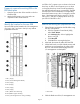
Identify the location for the new EEB
Up to two EEBs can be located in the I/O management
unit (one in slot 7 and one in slot 8) in any cabinet
populated with drives.
1. Slot 1 (empty)
2. Slot 2 (Control Management Blade)
3. Slot 3 (empty)
4. Slot 4 (empty)
5. Slot 5 (empty)
6. Slot 6 (empty)
7. Slot 7 (EEB for lower drive bay)
8. Slot 8 (EEB for upper drive bay)
9. Slot 9 (I/O management unit cooling assembly)
An EEB in slot 7 supports up to six drives in the lower
drive bay. An EEB in slot 8 supports up to six drives
in the upper drive bay. Drives must be populated in
the module from bottom to top, consecutively. The EEBs
and their ports are connected to the corresponding
drives from bottom to top, also. For example, connect
drive 1 (the bottom-most drive) to port ETH 1 of the
EEB in slot 7, and drive 2 (directly above drive 1) to
port ETH 2 of the EEB in slot 7.
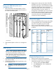
Remove the existing EEB (replacement only)
1. Take all drives connected to the EBB offline using
the Vary Off operation:
a. From the Operator Control Panel (OCP),
select Tools→Drives.
b. In the Drive(s) table, click to highlight the
drive to vary off.
c. Click Vary Off.
d. Click Yes in the warning dialog box.
2. Label and disconnect all cables from the EEB.
3. Lift the latch hooks out of the locked position and
push them up and away from the center of the
EEB. You will feel the EEB disengage from the
I/O management unit backplane.
1. Latch hooks
4. Slide the blade out of the I/O management unit.
Page 2