
HP Director Blade Installation Instructions (SALTA)
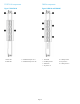
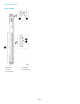
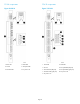


FC8-64FC16-48
FC4-48FCOE10-24
FS8-18FC8-16
FX8-24FC8-32
CR16–4FX8–24E
CR16–8
Installing the blade
CAUTION: Wear an ESD grounding strap
when handling the blade. On the director
chassis, the grounding connection is located
above the power connectors.
To install the blade:
1. Identify the ejector type for your blade, as
described in “Determining the ejector type” (page
13).
2. Locate an appropriate slot. Slots are numbered
from left to right when facing the port side of the
chassis.
For the HP 4/256 SAN Director: Install the blades
in slots 1 through 4 and 7 through 10.
For the HP DC SAN Backbone Director: Install the
blades in slots 1 through 4 and 9 through 12.
For the HP DC04 SAN Director: Install the blades
in slots 1 and 2 and slots 7 and 8.
For the HP SN8000B 8-Slot SAN Backbone
Director: Install the blades in slots 1 through 4
and 9 through 12.
For the HP SN8000B 4-Slot SAN Director: Install
the blades in slots 1 and 2 and slots 7 and 8.
3. Orient the blade so that the ports face outward
(away from the slot) and the flat (noncomponent)
side is on the left.
4. Proceed to Step 5 if the blade you are installing
uses ejectors only. (See “Determining the ejector
type” (page 13).)
For blades with both ejectors and slider switches:
a. Open the ejectors approximately 45 degrees,
align the flat side of the blade inside the
upper and lower rail guides in the slot, and
then, while applying slight pressure to the
left, slide the blade into the slot
(Figure 21 (page 14)).
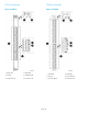
Figure 21 Removing and replacing a Director
blade with ejectors and slider switches
(FC4-16 shown)
2. FC4-161. 4/256 SAN Director
chassis
4. Ejectors (2)3. On/Off slider switch
b. Close the ejectors by pushing the handles
toward the center of the blade until the
ejectors lock.
The levering action of the handles seats the
blade in the slot.
c. Tighten the thumb screw inside each handle
using the Phillips screwdriver.
d. Turn the blade on by sliding up the slider
switch in the top ejector, covering the thumb
screw.
e. Proceed to Step 6.
Page 14