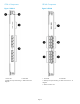
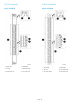
CR16-4 Components
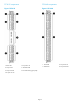
Figure 1 CR16-4
2. Status LED1. Power LED
4. QSFP Connectors3. QSFP port map and trunking
diagram
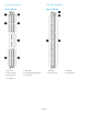
CR16-8 Components
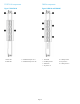
Figure 2 CR16-8
2. Status LED1. Power LED
4. QSFP Connectors 8—153. QSFP port map and trunking
diagram
5. QSFP connectors 0–7
Page 3