HP StoreOnce Backup system service and maintenance guide for HP StoreOnce 2700, 4500 and 4700 Backup Abstract This is the Maintenance and Service guide for the HP StoreOnce 2700, 4500 and 4700 Backup products. These products are also sometimes referred to as StoreOnce Backup single node rack products.
© Copyright 2014 Hewlett-Packard Development Company, L.P. Confidential computer software. Valid license from HP required for possession, use or copying. Consistent with FAR 12.211 and 12.212, Commercial Computer Software, Computer Software Documentation, and Technical Data for Commercial Items are licensed to the U.S. Government under vendor's standard commercial license. The information contained herein is subject to change without notice.
Contents 1 Spares part numbers for field replacement.....................................................5 HP StoreOnce 4700 24 TB Backup.............................................................................................6 HP StoreOnce 4500 24 TB Backup.............................................................................................8 HP StoreOnce 4500/4700 (24 and 48 TB) and 4500 (48TB) Expansion Modules..........................10 Storage shelves with HP StoreOnce 4700 Backup..........
Create a bootable QR USB Stick..............................................................................................37 Delete storage........................................................................................................................37 Boot the appliance and install the StoreOnce software ...............................................................38 Performing a configuration restore ............................................................................................
1 Spares part numbers for field replacement This is the Service and Maintenance Guide for the following models of HP StoreOnce Backup. The information in the appropriate ProLiant Maintenance and Service Guide should be the primary reference source for hardware issues on the related StoreOnce Backup System. Spares part numbers are available in the ProLiant guides. This guide contains only information that is not included in the ProLiant documentation.
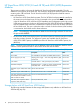
HP StoreOnce 4700 24 TB Backup NOTE: The following table contains the spare parts for the main components in the head server unit. See the HP StoreOnce 4500/4700 (24 TB) and 4500 (48TB) Expansion Module (page 10) for information about the hard disks in the storage expansion shelf and the SAS cabling from the head server unit to the expansion shelf. The disks in the head server unit are different to those in the expansion shelf.
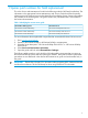
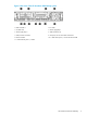
Figure 1 Rear view of the HP StoreOnce 4700 Backup system 1. RAID controller 1 2. FC card 1 3. FC card 2 4. RAID controller 2 5. 10 GbE card 6. Power supply bay 1 7. Power supply bay 2 8. USB connectors (4) 9. Video/monitor connector 10. iLO4 port, do not use for data connection 11. Serial connector 12. 1 GbE network port 1, connect for Quick Install 13.
HP StoreOnce 4500 24 TB Backup NOTE: The following table contains the spare parts for the main components in the server unit. A storage expansion shelf may be added to the configuration. Please refer also to HP StoreOnce 4500/4700 (24 TB) and 4500 (48TB) Expansion Module (page 10) for information about the hard disks in the storage expansion shelf and the SAS cabling from the server unit to the expansion shelf. The disks in the head server unit are different to those in the expansion shelf.
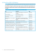
Figure 2 Rear view of the HP StoreOnce 4500 Backup system 1. RAID controller 1 2. FC card 1 3. 10 GbE card 4. Power supply bay 1 5. Power supply bay 2 6. USB connectors (4) 7. Video/monitor connector 8. iLO4 port, do not use for data connection 9. Serial connector 10. 1 GbE network port 1, connect for Quick Install 11.
HP StoreOnce 4500/4700 (24 and 48 TB) and 4500 (48TB) Expansion Modules The expansion module is the same for both the HP StoreOnce Expansion Modules. The only difference is the capacity of the hard disk. The StoreOnce 4500/4700 (24TB) Expansion Module contains twelve 2TB hard disks. The HP StoreOnce 4500 (48 TB) Expansion Module contains twelve 4TB hard disks.
Figure 3 Connecting the first storage enclosure to the HP StoreOnce 4700 Backup system 1. Head server unit 2. HD SAS port on RAID controller in slot 1 3. Expansion enclosure 4. Power on button 5. P1 port on expansion enclosure 6. Power connectors The HP StoreOnce 4700 Backup has two RAID controller cards and supports up to eight storage shelves. A second shelf is connected to the RAID controller in slot 4, again using a 2-meter cable.
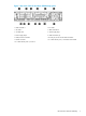
Figure 4 Cabling example for the HP StoreOnce 4700 Backup system 1. Power connectors 2. HD SAS port on RAID controller 1 3. HD SAS port on RAID controller 2 4. P1 port on expansion shelf (Note how subsequent shelves may be daisy chained) 5. P2 port on expansion shelf (connects to P1 on adjacent expansion enclosure) 6. Power on button Storage shelves with HP StoreOnce 4500 Backup The HP StoreOnce 4500 Backup base system contains 12 disks and has one RAID controller card.
Figure 5 Cabling example for the HP StoreOnce 4500 Backup system 1. head server unit 2. P1 port on expansion enclosure (Note how subsequent enclosures may be daisy chained) 3. P2 port on expansion enclosure (connects to P1 on adjacent expansion enclosure) 4. Power on button 5.
HP StoreOnce 2700 8 TB Backup NOTE: Storage expansion is not supported with this product. Table 5 HP StoreOnce 2700 8TB Backup spares part numbers Part Description SPN Processor (one per system) SPS-PROC E5-2620 6C 2.
2 General information NOTE: Make sure you have the correct Maintenance and Service guide for your product. There are a number of different models, and each has its own guide. Performance best practices HP recommends that you review HP StoreOnce Backup system Concepts and Configuration Guidelines, describing simple steps that can be performed to ensure that your HP StoreOnce Backup System is optimized as efficiently as possible. You can view this document from http://www.hp.com/support/.
Tasks that are unique to HP StoreOnce Backup The following tasks are described in this guide: • How to replace the motherboard • How to replace the HP RAID controller • How to replace the Cache module and SuperCapacitor • How to replace removable hard disks Rack stability Rack stability protects personnel and equipment. WARNING! 16 To reduce the risk of personal injury or damage to equipment: • Extend leveling jacks to the floor.
3 Identifying problems If you have configured recipients for SNMP traps or email alerts, they will be notified of any problems with hardware components. You can also use the StoreOnce GUI and StoreOnce CLI as described below. Example alerts The following alerts were triggered by a problem with a failed disk. The following event occurred: hardwarecomponent.
Hardware tree The following example shows the Hardware tree expanded to show the disk failure in a head server unit. The following example shows the Hardware tree expanded to show the disk failure in the expansion shelf. Using the StoreOnce CLI The following StoreOnce CLI commands can also be used to identify hardware problems and to walk through the hardware tree to obtain more details about a specific component.
2.
message type model serialNumber firmwareVersion location volumeName capacity 4. 5. = = = = = = = = The drive has failed. drive Port: 1I Box: 2 Bay: 2 LUN 1 1.00 TB After identifying the issue that needs to be corrected, follow the instructions in the relevant chapter of this guide. Be sure to check that all problems have been resolved. Re-run the StoreOnce CLI command: hardware show problems The output returned should now be blank.
4 Replacing the system motherboard For all products, refer to the appropriate ProLiant Maintenance and Server Guide for detailed instructions on replacing the motherboard. This chapter describes the following tasks that are specific to HP StoreOnce Backup Systems: • Update iLO4 IP details. • Update BIOS IDs on all products.
Table 6 DIMM slot locations (continued) Model HP StoreOnce 2700 Backup Processor Slots 2 12,9,1,4 1 12,9,1 The locations of DIMM slots are also shown on the StoreOnce hood label inside the server. Before replacing the motherboard—iLO4 licenses All products are shipped with paper copies of the iLO4 licenses. If you no longer have these licenses and the board is still working for the iLO4 GUI connection via its management Ethernet port, make a note of the license before you remove the motherboard.
Table 7 RBSU settings RBSU setting Sub-setting Power Management Options HP Power Profile Balanced Power and Maximum Performance Performance HP Power Regulator HP Dynamic Power Savings Mode PCI Device Enable/Disable Sub-sub-setting Current Embedded HP Smart Array P420i Controller Enabled Date and Time Advanced Options Change to...
5 The HP p1224 RAID controller Overview All HP StoreOnce Backup systems described within this guide use the HP p1224 RAID controller fitted with a RAID cache module and SuperCapacitor. The HP StoreOnce 4700 Backup has two RAID controllers; the HP 2700 and 4500 Backup have one RAID controller. Cables connect the internal SAS port on the RAID controller to the SAS storage in the server unit and the external SAS port on the controller to the SAS storage in the expansion shelf.
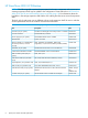
Figure 8 HP p1224 RAID card 1 Connector to external SAS storage 2 Connector to internal SAS disks 3 Cache module 4 SuperCapacitor (located in the center of the unit, clipped to the floor of the chassis behind the disk cage) 5 SuperCapacitor connector 6 LEDs Location of the RAID cards (server rear view) Figure 9 HP StoreOnce 4700 models, location of the p1224 controllers 1 RAID controller in PCIe slot 1 2 RAID controller in PCIe slot 4 Figure 10 HP 4500 models, location of the p1224 control
Figure 11 HP 2700 models, location of the p1224 controller 1 RAID controller WARNING! To reduce the risk of personal injury or damage to the equipment, consult the safety information and user documentation provided with the server and p1224 controller before attempting the installation. Identifying a RAID controller failure All HP StoreOnce Backup systems boot from a p1224 RAID controller that is also connected to some or all of the customer data storage disks.
Figure 12 Removing a p1224 card, example shows an HP StoreOnce 4700 Backup 4. Install the new p1224 card (1) and check that it is seated properly. Close the blue PCIe card retaining latch (2). Figure 13 Inserting a p1224 card, example shows an HP StoreOnce 4700 Backup 5. 6. 7. 8. Make sure the card is connected to the SuperCapacitor module and to the internal and external SAS data storage.
6 RAID cache module and SuperCapacitor failures Spares part numbers NOTE: Never move cache modules from one RAID controller to another within or between systems. The replacement spares part numbers are: • SuperCapacitor, spares part number 660093–001 • RAID cache, spares part number 633542–001 If replacing this module does not resolve the problem, it may be necessary to replace the RAID controller card. See the previous chapter for more information about replacement procedures and spares part numbers.
p1224 Storage System p1224 Storage System 02358fe6-0000-1000-b012-53344230334b 010e9a23-0000-1000-b01c-533442303034 DEGRADED OK # hardware show status 02358fe6-0000-1000-b012-53344230334b Name -------------------p1224 Storage System Drawer 1 Pools Controller 1 Dev-id -----------------------------------02358fe6-0000-1000-b012-53344230334b 50014380254FAD32 500143802050F740 pools-1 50014380254FAD30 Status -------DEGRADED OK DEGRADED DEGRADED OK # hardware show status 010e9a23-0000-1000-b01c-533442303034
These items ensure cache contents are maintained after a loss of power. The LEDs on the cache module flash when the SuperCapacitor is disconnected and POST error messages provide more information. Replacing the RAID cache module and SuperCapacitor 1. 2. 3. Remove the cover from the HP StoreOnce Backup system, as described in the appropriate HP ProLiant Maintenance and Service guide, and locate the module. Look at the LEDs on the module. If the LEDs are blinking amber the module should be replaced.
7 Expansion shelves The standard documentation supplied with field replacement parts for the expansion shelves provides all the required details, with the following important exception. IMPORTANT: The following parts are not hot-pluggable. The system must be taken offline before replacing them.
8 Disk replacement This chapter describes: • The storage RAID configuration • How to identify a failed disk • How to replace a disk • How to rebuild the RAID if several disks fail NOTE: For instructions on how to connect additional storage by adding a new capacity upgrade enclosure (not available with the StoreOnce 2700 Backup system), please see the printed documentation supplied with the additional storage.
operating system are lost and a “Quick Restore” of the appliance OS will be required before the unit can be used again. Ordering the correct replacement disk for a failed disk IMPORTANT: HP strongly recommends replacing a failed disk with a fresh disk from the factory. Do not substitute a disk from another RAID set.
Using the StoreOnce CLI The following StoreOnce CLI commands can also be used to identify specific disk locations, to walk through the hardware tree to identify the disk and enclosure and to flash the Beacon LED on and off. See Using the StoreOnce CLI (page 18) for a worked example. hardware show problems hardware show status hardware beacon Replacing a hot-plug hard disk 1. Identify the disk that has failed as described above.
NOTE: The illustration above shows disk removal in a StoreOnce appliance’s head server unit. The disk carrier is different when working with disks in an expansion shelf, as shown below. 3. Replace the failed disk with the new disk. Push the hard drive assembly (1) into the drive bay until it stops and press the HDD carrier latch (2) inward until it clicks. Figure 16 Installing a replacement hard disk NOTE: The illustration above shows disk installation in a StoreOnce appliance’s head server unit.
5. Run the StoreOnce CLI command, hardware show firmware, to check that the firmware on the new the new component is correct. Depending upon whether the disk was replaced in the server or the storage enclosure; it will be listed under the node/server or storage details. Run the StoreOnce CLI command, hardware update firmware, with appropriate parameters to update it, if necessary. See the HP StoreOnce Backup CLI Reference Guide for more details.
9 The QR ISO image In the rare occurrence of a complete system failure it may be necessary to re-install the product software. This task is normally carried out on the recommendation and under the supervision of HP Support. CAUTION: The Quick Restore process will delete all stored data and configuration settings returning your product to factory default settings.
Boot the appliance and install the StoreOnce software Make sure that power, network, keyboard and monitor, and all expansion enclosures are attached to the StoreOnce appliance, then insert the QR USB stick into one of the front or rear USB ports and power on the system. After the system powers up and completes self-tests it will boot from the USB key and launch the Linux installation process. After a few seconds a boot splash screen will appear offering the choice of Restore (R) or Exit (E).
3. Using the latest .txt file, manually apply all of the settings within this configuration text file using the StoreOnce CLI commands and instructions exactly as shown. This will ensure that the customer configuration is restored to its previous configuration. It is very important that this is done manually before attempting to restore the device settings automatically. NOTE: If the product has additional storage connected, please ensure Capacity Upgrade Kit licenses are applied. 4.
This will restore device settings for the appliance. 9.
10 Support and other resources Contacting HP For worldwide technical support information, see the HP support website: http://www.hp.com/support Before contacting HP, collect the following information: • Product model names and numbers • Technical support registration number (if applicable) • Product serial numbers • Error messages • Operating system type and revision level • Detailed questions New and changed information in this edition This is the first edition.
• HP Technical Support website: http://www.hp.com/support • Net-SNMP website: http://www.net-snmp.org • Single Point of Connectivity Knowledge (SPOCK) website: http://www.hp.com/storage/spock • White papers and Analyst reports: http://www.hp.com/storage/whitepapers Typographic conventions Table 11 Document conventions Convention Element Blue text: Table 11 (page 42) Cross-reference links and e-mail addresses Blue, underlined text: http://www.hp.
HP Insight Remote Support software HP strongly recommends that you install HP Insight Remote Support software to complete the installation or upgrade of your product and to enable enhanced delivery of your HP Warranty, HP Care Pack Service or HP contractual support agreement.
11 Documentation feedback HP is committed to providing documentation that meets your needs. To help us improve the documentation, send any errors, suggestions, or comments to Documentation Feedback (docsfeedback@hp.com). Include the document title and spares part number, version number, or the URL when submitting your feedback.