HP StoreOnce B6200 Backup System maintenance and service guide Abstract This guide is intended for users who maintain the HP StoreOnce B6200 Backup System. Some of the actions described are more appropriate to HP service specialists and require an HP Support login.
© Copyright 2012–2013 Hewlett-Packard Development Company, L.P. Confidential computer software. Valid license from HP required for possession, use or copying. Consistent with FAR 12.211 and 12.212, Commercial Computer Software, Computer Software Documentation, and Technical Data for Commercial Items are licensed to the U.S. Government under vendor's standard commercial license. The information contained herein is subject to change without notice.
Contents 1 Introduction...............................................................................................6 The HP StoreOnce B6200 Backup System ...................................................................................6 Hardware components..............................................................................................................7 Fault LEDs...........................................................................................................................
Front and rear views of HP B6200 server node (2 per couplet).....................................................27 6 Maintaining P2000/MSA Array Controller components................................29 Important considerations..........................................................................................................29 P2000 controller and JBOD replacement procedure....................................................................29 Hard disk drive (HDD) replacement.........................
Customer self repair................................................................................................................66 Subscription service................................................................................................................66 HP websites...........................................................................................................................66 Documentation feedback...................................................................................
1 Introduction This is the Service and Maintenance Guide for the HP StoreOnce B6200 Backup System. This product uses existing HP hardware components, which have their own documentation. This guide describes only those aspects that are specific to the HP StoreOnce B6200 Backup System. The HP StoreOnce B6200 Backup system comes as standard in a factory fitted rack. This document assumes that the B6200 has not been re-racked in any way.
NOTE: • The HP B6200 Backup System can only be installed in an HP B6000 rack. • An HP B6000 rack should only be used for HP B6200 Backup Systems and supported storage expansion shelves. • Do not install additional units, such as Ethernet network switches, in the rack. You will not be able to expand storage, if you do so. • The base couplet is always located in shelves 7 to 14 inclusive. • When installing a second couplet, it is located in shelves 27 to 34 inclusive.
components. Items which may be swapped online (hot-swappable) in a conventional server or rack installation may not be hot-swappable in an HP B6200 installation. • DL380 G7 ProLiant servers: the PSUs and the hard disk drives may be replaced individually while the couplet remains online. For all other component replacements, the service set on the affected node should be failed over to its backup node, and the server (node) taken offline.
2 Quick reference — configurable parts and replacement process checklists Node — HP ProLiant DL380 G7 Server For more details see Maintaining server (node) components (page 22). Configurable parts When replacing server parts use the HP ProLiant DL380 G7 Maintenance and Server guide, but be aware of the following HP StoreOnce Backup System specific information: Table 1 Server configurable parts Part Part number Description Comments DIMM 501536-001 8GB PC3-10600R,512Mx4 HDD 508009-001 500GB 7.2K 2.
All other components When a hardware component requires replacing on a specific node, please use the following process to complete the task. NOTE: Some of the following activities require access to the hpsupport account and may only be carried out by or under the supervision of HP service specialists. Task Refer to Put the node that you intend to work on into maintenance mode. If the node has a service set running on it, failover the service set to the other node first.
NOTE: If the node that is being replaced was running the active Management Console, it may have the blue LED lit after replacement. Simply press the blue LED on this node to switch it off manually. HP P2000/MSA Array Controller For more details see Maintaining P2000/MSA array controller components (page 29).
Configurable parts The only field replacement units in the internal network switches are the PSUs, which are standard parts. PSU and single network switches These two items are hot-swappable. Order the correct replacement part and follow the instructions in the relevant Switch guide. IMPORTANT: If changing a power supply, care must be taken to ensure that there is no interference with any of the PDUs and power cabling. Whole switch replacement process Task Refer to Power off the faulty network switch.
3 Firmware revisions The following firmware revisions are current as at October 2013, software build 3.9.0. Subsequent updates to this list will be via Release Notes until the next edition of this guide. You should also check Engineering and Service Advisories for any exceptions or updates to this list. Table 3 Firmware revisions Component firmware Spares part number Firmware revision DL380G7 Motherboard BIOS N/A 2011.05.05 DL380G7 Motherboard iLO3 N/A 1.5.
4 Pre-requisites Tools required The following toolset is recommended, although the items required to complete the tasks will vary for each installation. Hardware tools • Torx and Phillips screwdrivers • Blank DVDs (not DVD-R) in case a QR-DVD ISO image must be loaded • Cables 1. CAT5E or CAT6 1Gb ethernet cable to connect to the internal network switch 2. RS232 DB9 serial — RS232 DB9 serial cable to connect to the first rack network switch 3.
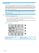
1. Use a Cat 5E or Cat 6 1GbE cable to plug your laptop into a spare 1GbE port on the internal network switches in Rack 1. Available ports depend upon the number of racks and couplets in the configuration, however, ports 13 to 16 should be available. NOTE: Do not use the internal network switches in Rack 2 because they contain 10GbE ports only and are not suitable for this type of connection. 2. 3. Wait for the ethernet link to be established. (Both green and amber LED on the ethernet connector are on.
6. You are now accessing the active Management Console via the internal network. 7. From here, you can perform all StoreOnce CLI commands. Offsite (remote) troubleshooting and repair For remote repair you must access the system using the external network management console, the Management VIF. 1. Use a supported web browser to log in to the GUI using the Management VIF. Use puTTY or another ssh connection to log in to the Storeonce CLI using the Management VIF.
2. You are now accessing the active Management Console via the external network and can perform all StoreOnce CLI commands. HP Support users only Once you have accessed the Active Management Console from either the internal or external network, you can use the hpsupport command to access the Linux shell to perform Linux commands and navigate to other nodes, storage or network. For a fill list of the internal network addresses see Internal network static IP addresses (page 17).
Table 4 Internal network static IP addresses (continued) Network switches Device Port/Component Address Device Port/Component Address Node 1 bond0 10.154.4.1 Node 5 bond0 10.154.4.5 Node 1 iLO 10.154.5.1 Node 5 iLO 10.154.5.5 Node 2 bond0 10.154.4.2 Node 6 bond0 10.154.4.6 Node 2 iLO 10.154.5.2 Node 6 iLO 10.154.5.6 First P2000 shelf Controller A 10.154.2.1 First P2000 shelf Controller A 10.154.2.5 First P2000 shelf Controller B 10.154.3.
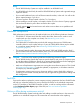
Figure 3 Hardware Details (GUI) 3. Make a note of the relevant information on this page. In particular, you need the: • Serial Number to confirm that you have replaced the correct component • Firmware Version to confirm that the replacement component is running the same firmware. System health check (HP Support users only) From software revision 3.2.0 a system health check can be run from the hpsupport user level.
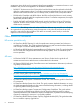
3. An example attachment.txt file is shown below. Preparing for maintenance activities Putting a node into maintenance mode Ensure that you know which node you are required to work on. See How are hardware problems notified (page 18). Use the following command sequence to ensure a node is in maintenance mode and cannot be used by the system during failover. 1. Log in to the Management VIF (if you are using a connection to the internal network switch, this will be 10.154.1.1).
2. Use the GUI Home page to ensure that the failing node is idle; no Service Sets are running on the node that is to be repaired. If it is not idle, stop all backups, restore and replication jobs. Use the StoreOnce CLI command to put the node offline. hardware enable failover hardware failover nodeX 3.
5 Maintaining server (node components) — HP ProLiant DL380 G7 Server The HP B6200 Backup System uses a standard DL380 G7 for each node. The information in the HP ProLiant DL380 G7 Server Maintenance and Service Guide should be the primary reference source; it also contains spare part numbers. This guide contains only information that is not included in existing documentation. http://h20000.www2.hp.com/bizsupport/TechSupport/DocumentIndex.
Table 5 Server configurable parts (continued) Part Part number Description Comments FC card 489191-001 82Q FC Q-Logic Dual 8GB FC card Motherboard 599038-001 DL380 G7 motherboard Flash Backed Write Cache 578882-001 512MB flash backed write cache BIOS, iLO3 settings and MAC addresses for any network ports must be configured IMPORTANT: When replacing the motherboard (or individual cards) be sure to always replace cards into the same slot from which they were removed.
4. Press to save the changes, and exit. BIOS settings IMPORTANT: to the server. 1. 2. 3. 24 Configure the BIOS settings BEFORE connecting the FC, network and SAS cables Ensure that you have the latest BIOS revision installed, see table below. Install the latest BIOS revision from the relevant product site. All BIOS revisions can be found at http://www.hp.com/ support/downloads (under Storage — Disk Storage Systems — Disk to disk Backup — HP StoreOnce Backup Systems). Reboot the system.
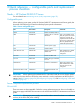
Table 6 RBSU settings DL380 G7 BIOS setting RBSU menu items Product ID Advanced Options Service Options Product ID 652428-B21 Chassis serial number Advanced Options Service Options Serial Number Enter the number that is identified on the chassis of the server Cluster serial number Server Asset Text Server Info Text Other Text — Line 1 Enter the System id for the cluster. This can be found on the GUI on the Device Configuration page (see example screenshot below).
4. Repeat these two steps to find the address of the other three 1GbE ports,eth1, eth2 and eth3, and update the HWADDR in the associated ifcfg files. Updating motherboard components firmware If a motherboard is replaced and the component firmware is at a different revision, this can be manually updated using the smart components stored on the system. 1. Log in to the node and access the shell via the hpsupport role.
In the following example we are replacing a card in slot 1 and need to configure the eth4 and eth5 ports. IMPORTANT: If this is not done, the new 10Gb will not be part of the bond0 (for internal network) and therefore cannot provide a dual path in case the other 10Gb HBA fails. You will see an Alert event in the Event log such as: HBA link 50.06.05.b0.03.5e.a1.e0 on host hp99ba03c272-2 status is stale 3. 4. Log in to the StoreOnce CLI, enter hpsupport and access the shell.
Figure 6 Rear view of the HP B6200 server node 1 FC port, top card (identified as FC Port 1 on the StoreOnce GUI) 2 FC port, bottom card (identified as FC Port 2 on the StoreOnce GUI) 3 Unused FC ports (cards 1 and 2) 4 10 GbE port eth4, (reserved for internal use) NOTE: StoreOnce software v3.9.0 and later: these ports are available for use. See HP StoreOnce Backup system user guide for details.
6 Maintaining P2000/MSA Array Controller components HP Storage P2000/MSA Array Controllers service and maintenance information (a selection of guides) can be found at: http://h200003.www2.hp.com/bizsupport/TechSupport/DocumentIndex.jsp? contentType=SupportManual&lang=en&cc=uk&docIndexId=64902&taskId=101& prodTypeId=12169&prodSeriesId=4118559 Each controller or JBOD shelf has two arrays, each with six disks. One disk may fail in each array without affecting system functions.
1. Login to GUI and navigate to the appropriate Hardware — Couplet — MSA — Enclosure page to identify the hard disk that is in LEFTOVER state. 2. 3. Click on the Clear Left Over Disk button to re-instate the HDD into the RAID Set. After 1-2 minutes, a pop up window will appear with the status of the operation. CAUTION: Do not use any other button to clear this state. Do not use the option on the RAIDset page to rebuild a RAID. You will lose all data within the couplet if you use this button.
To update HDD firmware The standard rpm packages within the HP StoreOnce B6200 software upgrade cannot be used to update the firmware of the HDDs within the P2000 storage. HDD firmware update is a manual process that should take place when there is NO disk I/O activity over the SAS interfaces. 1. Search www.hp.com for the relevant StoreOnce Service Advisory for the location and procedure to upgrade the HDD firmware. For the examples in this section we are using firmware update 0008 on ST31000424SS. 2. 3.
• IP address = the internal network address of the P2000 controller where the HDDs that you wish to update are situated • User Name = admin • Password = !admin NOTE: You can also use the command line option: cp019925_Muskie_0008.exe /target /user admin /passwd !admin Where is the internal network address of the P2000 controller where the HDDs that you wish to update are situated. 8. At the end of the process, the executable will give feedback on ‘successful’ / ‘unsuccessful’ updates.
Firmware revision It should not be necessary to update the firmware if you are replacing a component only. Any firmware updates that apply to the P2000 controller or JBOD are automatically applied whenever there is a new release of the HP StoreOnce B6200 Backup System software (which includes firmware updates). HP B6200 storage controller array (one for each server node) There is a storage controller array with twelve SAS storage disks connected to each server node.
Figure 10 Rear view of the capacity upgrade kit 1. Fans 2. Power sockets 3. Serial port for service support 4. I/O module B SAS IN port (from P2000 controller or previous P2000 JBOD) 5. I/O module A SAS IN port (from P2000 controller or previous P2000 JBOD) 6. I/O module A SAS OUT port (to next P2000 JBOD) 7.
Figure 13 SAS cabling P2000 controller (Node B) to JBOD shelves P2000 controller and JBOD cabling 35
7 Maintaining internal network switches The only field replacement units in the internal network switches are the PSUs. If the complete switch is replaced, it is essential to ensure that it is configured correctly for use with the HP StoreOnce Backup System. Particular care must be taken to restore the cabling to the same configuration. The internal network switches are whole unit exchanges, and must be configured prior to connecting into the B6200 internal network.
• 3. 4. 5. When connecting to the network switch in the second rack (E6600-24XG or J9265A): use a RJ45 – RS232 DB9 Serial Cable Using a suitable hyperterminal, minicom, telnet program, setup a serial connection and open a session using the following parameters: • Baud Rate = 115200 baud • Data Bits = 8 • Stop Bits = 1 • Parity = N There are no login details required, hit Enter to receive the prompt. If you arrive at a menu page, type 5 to enter the command line (CLI).
4. At the prompt enter boot system flash primary 5. The switch will reboot. It will take approximately 5 to 10 minutes before the switch will be able to respond and be logged back into via the telnet or serial port session. At the prompt enter show system information 6. Enter the following sequence of commands to configure the IP service for the switch and show the results. NOTE: in the following command sequence is the required IP of the switch replaced.
7. You now need to configure the trunking. The command sequence varies according to the number of racks and the location of the switch for which the trunking is being configured. • Single rack with one or two couplets: Enter the command trunk ethernet 17-24 trk1 trunk followed by show run to display the required configuration. • Two racks You must configure the trunking for both the first rack and the second rack and you must configure both switches in each rack.
◦ Rack 2 of a two-rack configuration Enter the following commands followed by show run to display the required configuration. For “R2 Sw A” (10.154.6.3): For “R2 Sw B” (10.164.6.4): This will return a display similar to the following: 40 8. Enter the following sequence of commands to configure and show the Spanning Tree. 9. Enter the following commands to write the configuration to memory and exit the configuration.
10. You may now plug in all the ethernet cables into the switches. If you require additional assistance to show where the cables go, please see the Installation & Configuration Training Module. Switch cabling diagrams Figure 14 Example cable label, internal network switch The factory uses combinations of the following terminology for labelling cables. • RSw, where R is the Rack number, 1 or 2, and Sw is the internal network switch within the rack, which may be A or B.
Single rack installations Figure 15 1GbE internal network cabling (4 nodes) 42 Maintaining internal network switches
Figure 16 10GbE internal network cabling (4 nodes) Two rack installations NOTE: In a one-rack installation, the network switch in Rack 1 supports both the 1GbE and 10GbE internal connections. It a two-rack installation, the network switch in Rack 1 supports internal 1GbE connections only.
Figure 17 1GbE internal network cabling (8 nodes) Figure 18 10GbE internal network cabling (8 nodes) 44 Maintaining internal network switches
8 General reference In this chapter: • Accessing the Management Console (page 45) • What happens during failover (page 45) • Power off (page 46) • Power on (page 46) • Software update process (page 48) • Pulling a Support Ticket (page 50) • Serial numbers (page 52) Accessing the Management Console The Management Console may be accessed via the GUI or the StoreOnce Command Line Interface (CLI). The user access for both GUI and StoreOnce CLI is via the Management VIF and the same roles apply.
It is very important when carrying out service and maintenance activities on a node or storage controller, that autonomic failover is disabled until the activity is completed. Also, if the maintenance activity is on the server that is running the active Management Console, that node must be failed over in a controlled manner before you start.
IMPORTANT: Items 1 to 3 power up immediately on connection to the PDU. Servers have a power on button. Please wait 10 minutes BEFORE powering up the servers. Powering up servers 1. Power up the server using either: • The power on button on each server to trigger a cold boot and automatically power up. • StoreOnce CLI commands to power up a node remotely.
hardware failback nodeX Software update process Software updates can only be performed through the StoreOnce CLI using the Admin user account. Software updates are delivered to customers in the form of a single rpm package, which may contain multiple rpms. Everything is updated in the same way, using the rpm package: the software, third party components and the firmware for hardware components. All nodes are updated in parallel. A software update is NOT an online process.
Run the StoreOnce CLI software update commands To ensure smooth running of the software upgrade process, HP recommend that the HP B6200 Backup System has failover disabled prior to the upgrade. Once the software upgrade has completed successfully, failover should be manually turned back on. The status of failover can be checked using the StoreOnce CLI command: hardware show node status. The value shown in the HA (high availability) column indicates whether failover is on or off for the relevant node.
• From the GUI: Check on the Event log for a confirmation message that the software revision number has updated • Take a support ticket and look at the file Update_pkg__
Name Description requirements.If this number is exceeded, an automatic purge/overwrite occurs with the oldest being overwritten. Sending cluster configuration After each data collection, a zip file containing specified B6200 and system command by email enabled outputs representing the cluster configuration may be sent by email. This can be enabled or disabled. If enabled, you must set the appropriate parameters. (Note:this can be a large package of information.
3. Once the collect is complete, highlight the ticket row to be downloaded, then press Download. This will pull it across to your local server, where the file can be stored. Download cannot be permitted when a manual Collect is in progress. NOTE: It is important to set Security configuration options correctly if you are using Internet Explorer as your web browser. If you do not, the download will fail without an error message. 1. Add https://VIF https://node1 , https://node2 2. Enable download.
Example 1 You have an installation with the minimum configuration, which is a single couplet product and consists of three SKUs: • EJ021A comprises of two network switches with a common bundle number showing on each switch • AF092A/BW908A comprises of a 42U rack and PDUs - the PDUs and rack have their own serial numbers • EJ022A comprises of two DL380 G7s and two storage controller shelves with a common bundle number showing on each unit and a toe-tag tied to each unit Q1: If you telephone Support, wh
Figure 20 Location of bundled serial numbers 1 Internal network switches, rack 1 and rack 2. The bundled serial number for each pair of switches can most easily be read underneath the lower switch. 2 Capacity upgrade enclosures (optional). The bundled serial number for each pair of JBODs in a capacity upgrade enclosure can most easily be read on the top of the upper JBOD. This becomes more difficult as you add each new pair of JBODs. HP suggests the customer keeps a record of these serial numbers.
It can also be obtained using the following StoreOnce CLI command and response sequence: # system show config System ID : hp78e7d1e6928e Description : hp78e7d1e6928e CLI output : text NOTE: In early versions of the software, the System Id was called the Cluster ID.
9 Using the QR ISO image The following procedure describes how to obtain the QR ISO image and carry out a Quick Restore. The QR ISO image is downloaded to a blank 4GB USB stick (or to a blank DVD). The Quick Restore (QR) ISO image is available to re-image the software on a StoreOnce appliance to a known good state. It is only used in the unlikely event of a node’s root file system becoming corrupted or lost; for example if multiple OS disk failures have occurred.
3. Insert the QR USB sticks into one of the front or rear USB ports of each node of the HP StoreOnce cluster. If using QR DVD disks, place a QR-DVD in the DVD drive on each node of the HP B6200 cluster. 4. Power down all nodes. a. Press and hold the power button on each server b. Wait until the buttons are amber on all servers 5. Connect into the internal network a. Connect your laptop into the internal network switch at the top of Rack 1. b. Rack 1 has the network switch with 1GbE ports c.
Or delete volumes ,, and so on. 5. Verify that all the volumes have been deleted. show volumes No volume names should be displayed. 6. 58 Exit the P2000 controller and repeat the task for each of the IPs defined above.
OR • Using the P2000 GUI Storage Management Utility (SMU) 1. From a browser window, connect to the P2000 SMU using the IP address shown above. 2. 7. 8. Under the Provisioning tab click on Delete Volumes. Connect a monitor and keyboard directly to the VGA output and USB port of the bottom node of the rack. Power up the node (server) at the bottom of the StoreOnce rack. a. If there are two racks, power up the node in rack 1. (Rack 1 has the switch with 1GbE ports.) b.
c. d. 9. Run the installation script: a. After reboot the installation script will prompt to start. b. 60 Press [R] and confirm to re-image this first node. After re-image, accept the prompt to reboot the node. Select 2) Continue Installation.
10. Run the auto-installation script to create a cluster: a. After configuring the node, the installation menu will be displayed: b. Select 2) Create Cluster. IMPORTANT: c. This is the FIRST node. So, a cluster must be created, not joined. Once the auto-installation script completes and the login prompt appears, move to the next node 11. Connect a monitor and keyboard directly to the VGA output and USB port of the next node up from the bottom of the rack which has not already been re-imaged.
13. Run the auto installation script to add a node to the cluster: a. After reboot, the installation script will be displayed: b. Select 2) Join existing cluster. IMPORTANT: This is an additional node, which must be joined to an existing cluster. (Do not create a new cluster.) c. Once the auto-installation script completes, the login prompt appears. 14. Repeat steps 11, 12 and 13 until all the nodes in the cluster are re-imaged, working from bottom to the top. 15.
f. g. h. An enclosure pair with 1TB drives will have 24 TB of raw storage and 16 TB of raid storage. Determine the number of enclosure pairs in a couplet and calculate the sum of storage. Verify that this amount of RAID6 storage is approximately the same as that displayed for the given service set pair (couplet) For example: in a couplet with 48 TB base couplet with 24 TB of storage expansion, each node would have two enclosure shelves.
8. Run the auto installation script to join the repaired node to the cluster: a. After reboot, the installation script will be displayed: b. Select 2) Join existing cluster. c. 9. Once the auto-installation script completes, the login prompt appears. Log into the StoreOnce CLI. • Account: Admin • Password: admin 10.
Support and other resources Document conventions and symbols Convention Element Blue text: Document conventions and symbols Cross-reference links and e-mail addresses Blue, underlined text: http://www.hp.
Backup System, it is a good idea to read this guide before you configure your system. It describes the StoreOnce technology. • HP StoreOnce Backup System CLI Reference Guide: This guide contains a list of the available CLI commands with instructions on using them. • HP StoreOnce B6200 Backup System User Guide: This guide contains detailed information on using the Web Management Interface. It also contains troubleshooting information, including details on replacing failed or failing hard disks.