HP StoreOnce B6200 Backup System Installation Planning and Preparation Guide and Checklists nl Abstract This guide is intended for customers so that they can prepare for HP service specialists to install the HP StoreOnce Backup System. It will help them ensure that all environmental and networking prerequisites are in place before HP service specialists arrive to install the product and carry out the initial configuration. This document assumes that the product has not yet been delivered.
© Copyright 2011–2013 Hewlett-Packard Development Company, L.P. Confidential computer software. Valid license from HP required for possession, use or copying. Consistent with FAR 12.211 and 12.212, Commercial Computer Software, Computer Software Documentation, and Technical Data for Commercial Items are licensed to the U.S. Government under vendor's standard commercial license. The information contained herein is subject to change without notice.
Contents 1 The HP StoreOnce B6200 Backup System......................................................5 Warnings and cautions.............................................................................................................6 2 Product specifications..................................................................................8 Product dimensions...................................................................................................................8 Product weight...................
Documentation feedback.........................................................................................................
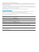
1 The HP StoreOnce B6200 Backup System An HP service specialist will install the HP B6200 Backup System. It is supplied partially configured and is made up as follows: • One or two HP B6000 Extended Rack Assemblies with stabilizers • The rack contains at least one base couplet (consisting of two server nodes and two dual controller disk arrays each with 12 disks) and two switches. The two switches are dedicated to support a network internal to the product.
Figure 2 Fully expanded couplet in rack Warnings and cautions The customer is not normally expected to unpack and handle the product. However, should this prove necessary, care must be taken to avoid damage to people and equipment. For this reason, safety and handling instructions are included below.
unpack the product. You should also read the Safety Booklet on Documentation CD that is supplied with your product. WARNING! To reduce the risk of personal injury or damage to the equipment, before installing equipment be sure that: • The leveling jacks are extended to the floor. • The full weight of the rack rests on the leveling jacks. • The stabilizing feet are attached to the rack if it is a single-rack installation. • The racks are coupled together in multiple-rack installations.
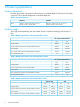
2 Product specifications Product dimensions Note that this product is provided in extended racks: an installed depth of 1240 mm (50.50 inches) is required. This is 240mm deeper than a standard depth rack. Table 1 Physical dimensions Rack Shipping Installed 218 cm x 146 cm x 86 cm (h x d x w) 85.80 x 57.50 x 33.90 inches 200 cm x 124 cm x 61 cm (h x d x w) 78.80 x 50.50 x 23.60 inches nl nl Product weight The weight varies depending upon the number of racks, couplets and storage, and the type of PDU.
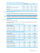
Table 5 Weight specifications with modular PDUs, Rack 2 24A and 32A 40A kgs lbs kgs lbs Single couplet 291.06 640.19 274.74 604.18 Single couplet with maximum storage added 471.06 1036.19 454.74 1000.19 Two couplets 409.60 900.98 393.28 864.98 Two couplets with maximum storage added to couplets 771.60 1697.38 755.28 1661.38 Power/PDU requirements Two power outlets are required for each couplet.
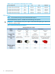
Table 9 Power specification at 240V, both racks installed 2–rack configuration A W AV BTU/hour 3 couplets with minimum storage 24.15 5636.90 5848.96 20406.86 3 couplets with maximum storage 40.11 9326.90 9677.81 34261.44 4 couplets with minimum storage 30.77 7169.66 7439.38 25823.15 4 couplets with maximum storage 52.04 12089.66 12544.50 44295.92 PDU options NOTE: HP recommends using one of the Monitored PDU options.
Figure 4 Dual and Quad Modular PDU part numbers Power/PDU requirements 11
3 Connecting to your network IMPORTANT: The network configuration is probably the most complex aspect of installation. Please take time to read this chapter before completing the Network checklist later in this document, see Network requirements (page 28). Each couplet is a paired combination of two nodes that are directly connected in failover pairs. If one node fails, the system is designed to failover to the other node without any external interaction from the customer.
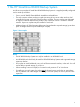
The cabling required to connect to each switch is pre-installed. The cabling to each node is shown in the following diagram. The ports illustrated are reserved for use with the internal network switch. CAUTION: You should NEVER unplug the default factory cabling and you should NEVER connect the customer network to the internal network switches at the top of the racks. Figure 5 Factory default internal network cabling of each node (must not be altered) 1. 10GbE connection to internal network switch 2.
VIF addresses • The VIF addresses are key to ensuring continued performance and availability in the event of failover and are assigned as part of the network configuration process. • There are two instances of VIF addresses: the Management Console VIF and Data Path VIFs. • The B6000 Management Console uses the Management VIF address to access the Backup System from the customer’s network for all manageability tasks.
connections; if the active network link fails then traffic moves to the backup port. It is used as the default bonding mode for Templates 1, 3, 4 and 5. • Mode 4 (IEEE 802.3ad Dynamic Link Aggregation) This bonding mode is also known as LACP and requires a special external switch configuration. It provides a link aggregation solution, increasing the bond physical bandwidth but can only work if all the ports in the bond are connected to one switch or switches joined by an interswitch link.
Some examples • Customer has a 10GbE and a 1GbE network and only wants data to be accessible remotely: Use Template 1, but configure one gateway only to the 10GbE network for data • Customer has a 10GbE and a 1GbE network and wants both data and management to be accessible remotely: Use Template 1 and configure two gateways. Decide whether data or management should use the 'default' gateway.
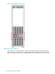
Figure 6 Template 1 cabling to customer's networks 1 and 2 bonded 10 GbE ports, normally to customer's data sub-net 3 and 4 bonded 1 GbE ports, normally to customer's management sub-net light blue cables See Factory default cabling (page 12). These should not be disconnected. Template 2, uses 1GbE network only Template 2 supports users who have a 1GbE network only. The same network is used for data and management. The default bonding mode for this template is Mode 6.
Figure 8 Template 3 cabling to customer's networks 1 and 2 bonded 10 GbE ports to customer's data and management network light blue cables See Factory default cabling (page 12). These should not be disconnected. Template 4, uses two 1GbE networks Template 4 supports users who have two 1GbE networks. One 1 GbE network is used for data; the other is used for management. The gateway must be in the same sub-net as the network that is being used to connect to remote sites.
Figure 10 Template 5 cabling to customer's networks 1 and 3 bonded 1 GbE ports to customer's data and management network 2 and 4 not used light blue cables See Factory default cabling (page 12). These should not be disconnected.
NOTE: Templates 1 and 4 are for installations that connect to two sub-nets; physical port connections are required for both the 1GbE management and the 10GbE data networks. Templates 2, 3 and 5 are to a single network and, therefore, do not require separate physical port connections for access to the B6000 Management Console. All data path IP addresses must be contiguous.
Number of physical ports for each template The number of physical connections that are required varies depending upon the template selected and the number of couplets in the system. This number should not be confused with the number of IP addresses required.
4 Fibre Channel connection The physical FC connection to the HP B6200 Backup System is straightforward; there are four FC ports per node. However, care must be taken to ensure there is no single point of failure in switch or fabric zoning that will negate the failover capabilities of the HP B6200 Backup System and its autonomic restart ability. NOTE: Only two ports are available when using software revisions prior to 3.9.0. Upgrading to 3.9.
5 Preparing for installation The customer should ensure that a keyboard and monitor are available for use as a management console during the initial configuration stage. NOTE: HP does not recommend using a KVM installed in the rack because this will cause problems when a second couplet is added. In a fully expanded rack there is no space for locating a KVM within the rack.
change this via the GUI or CLI. Any password change applies to both the GUI and StoreOnce CLI. • Operator: This is the default account for a local user whose access will be restricted to monitoring and viewing StoreOnce. It provides limited access to the GUI and StoreOnce CLI. The initial user name and password is Operator and operator, but the user may change this via the GUI or StoreOnce CLI.
6 Checklists for completion prior to installation Use the following checklists to ensure that: • You have understood the location, power and networking/fibre channel requirements of the product at the time of placing the order • Prepared the environment and the information that the service specialist requires to install and configure your system NOTE: An electronically fillable version of this section is available for this product from http:// www.hp.com/support/manuals.
Table 14 Product configuration (continued) Note any requirements for: • Capacity upgrades and licenses • Replication and Catalyst licenses • Security license (available with StoreOnce software v3.9.0 and later) • Couplet(s) to be installed • Additional cabling requirements and make sure they are pre-laid Location At the time of placing the order, make sure that there is a suitable location with access to install the product. This must be a data center environment and not an office environment.
NOTE: The Power/PDU requirement varies depending upon the number of racks, couplets and storage, and the input voltage. 1. PDU option and connector type Please provide details of: PDU option: .................................................................................................................. Connector plug type:............................................................................................................. Connector socket type:....................................................
Network requirements Network requirements must be defined and sufficient IP addresses must be available. This is complex. Please read Connecting to your network (page 12) before completing the details below. Please note that Template 5 is available for software revision 3.3.0 and greater. IMPORTANT: It is essential that the information in the following checklist is completed and given to HP Support Services prior to the install.
7. Please enter networking parameters below. They are required for the network configuration script. 1. All templates: Virtual Management Console VIF IP address, recommended to be the first address in your contiguous IP range.............................................................................................. 2. Templates 1 and 4 only, Management sub-net parameters If provided, must be on same sub-net as Virtual Management Console VIF nl nl Start IP adress........................................
Fibre Channel If you are not using VTL for backup, please ignore this section. 1. You have the correct number of physical FC connections; 8 per couplet. NOTE: 2. StoreOnce software prior to v3.9.0 only supports four FC connections per couplet. Fibre Channel is configured correctly for Virtual Tape Libraries (VTL) and the configuration supports failover. See Fibre Channel connection (page 22).
About this guide Intended audience This guide is intended for customers so that they can prepare for HP service specialists to install the HP StoreOnce Backup System.