DISCLAIMER: This PDF was generated on February 28, 2001.
Superdome Configuration Upgrades and Add-ons SuperDome Configuration Adding additional capacity to an existing system requires careful consideration and planning. A Solution Implementation Plan (SIP) should be developed before visiting the customer site. A Solution Manager assigned by HP's Global Sales Services (GSS) working with the account owner, will identify the system configurations, services, and training required to meet the customer's needs.
Superdome Configuration For best performance, partitions should be either single cell or greater powers of 2: 2, 4, 8, and 16 cells. Memory interleaving is performed by taking either four or six physical address bits and using them to index into a cell mapping table entry consisting of 16 or 64 sub-entries. For a single cell partition, each sub-entry is loaded with only one cell. A two-cell partition alternates between the two cells.
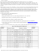
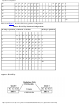
Superdome Configuration 12 A A A A A A A A 13 A A A A A A A A 14 A A A A A A A A A 15 A A A A A A A A A 16 A A A A A A A A A A A A A A 1 A A A A A 1 A A A A A 1 A A A A A A 1 A A A A A A 1 48 Table 2 and Figure 1 show the SD 32 way partition configurations.
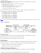
Superdome Configuration XBC-XBC Link Load Equation A simple calculation can be made to evaluate whether or not a particular configuration will have bottlenecks. 1. The number of cells on one quad, Qx, that talk to another quad Qy 2. The total number of cells is Qt 3. The number of links between the two quads is L. (Always 1) 4. Link load is Qx*Qy/Qt/L. (Link load = 4*4/8/2 = 1). Strive always for a link load of 1.0 or less. The lower the link load, the better off the system.
Superdome Configuration Other configuration resources include: The superdome Servers Configuration Guide. The superdome technical white paper. Upgrades and Add-ons Installing Additional Cell Boards http://superdome-test.fc.hp.com/sd_web/content/00/0A/DU/idd/400.
Installing Additional Cell Boards Upgrades and Add-ons Installing Additional Cell Boards Adding additional capacity to an existing system requires careful consideration and planning. A Solution Implementation Plan (SIP) should be developed before visiting the customer site. See SuperDome configuration for configuration information and resources. Add-on Overview This section gives an overview of the installation of additional equipment to a system: Step 1. Check and record the existing configuration.
Installing Additional Cell Boards Installing the New Cell Board This section contains information on installing a new cell board and assumes that the add-on planning has been performed. Adding a cell board to an existing system may require that you remove cell boards already in the system to redistribute cell boards and memory. If you must remove existing cell boards to redistribute memory or cell boards, go to Installing Add-on Cell Boards Requiring DIMM Redistribution.
Installing Additional Cell Boards are large and easily damaged. Example 1 Incorrect Memory Distribution Across Partitions If a two cell partition has 2 Gbytes of memory on one cell and 16 Gbytes on another, 4 Gbytes will be interleaved (two from each cell) and 14 Gbytes will be assigned to one cell only. This results in inconsistent bandwidth and latency problems. For more details on memory configuration see Overview: Memory.
Installing Additional Cell Boards Step 1. Step 2. Release the locking levers located at the top and bottom of the cell board. Step 3. Remove the cell board and place it on a flat surface. Employing the proper ESD procedures, carefully remove or install DIMMs as necessary. For more details on memory configuration see Overview: Memory. For detailed instructions on how to remove Step 4. and replace DIMMs see Replacing a DIMM. Installing the Cell Board For each cell board complete the following steps: Step 1.
Installing Additional Cell Boards The procedure covers the addition of a cell that will be a single cell partition or already has a DIMMs configuration that matches the cells in the target partition. Preliminary Procedures This procedure must be completed prior to installing the new cell board. Step 1. Visually inspect the new part for proper part number and revision. Step 2. Using your add-on configuration as a guide determine which slot will receive the new cell board. Step 3.
Installing Additional Cell Boards Verifying the Task To verify the functionality of system complete the following steps: Step 1. If there are any Mesa online tests for the cell board and memory, run them now. Step 2. Resolve any diagnostic faults. Step 3. Label any defective material with the proper information and package it for return to the local parts hub. Step 4. If applicable, update the system logbook (Gold book). Step 5. Clean the work area including the removal of all packaging material. Step 6.
Overview: Memory Upgrades and Add-ons Overview: Memory On SuperDome systems, each cell board holds a portion of the total system memory. Part of the memory address identifies the cell so that packets, which reference memory, can be routed to the correct cell board. Once the packet reaches the appropriate cell, the memory address is converted into the proper memory physical address, i.e., rank, bank, column, and row.
Overview: Memory Each path has its own address bus, control bus, data bus, M2s, and DIMMs. The cell controller (CC) runs each path 180 degrees out of phase, with respect to the other, to facilitate pipelining in the CC. Address and control signals are fanned out through registers to the DIMMs. Data is transferred between the CC and the DIMMs through the M2 ASICs. The M2s are bit sliced and four are required to form one 72 bit CC memory data bus (MID).
Overview: Memory Memory Configurations Memory must be installed in sets of four DIMMs, called DIMM ranks. The DIMM ranks are installed in numerical order, starting with rank 0 and proceeding up to rank 7. Figure 2, Memory Configuration - 1 DIMM Rank, Figure 3, Memory Configuration - 2 DIMM Ranks, and Figure 3, Memory Configuration 2 DIMM Ranks, show examples of the memory configurations for 1, 2, and 3 DIMM rank configurations. Currently, SuperDome supports 512Gbyte DIMMs using 128Mbit SDRAM parts.
Overview: Memory Figure 4 Memory Configuration - 3 DIMM Ranks http://superdome-test.fc.hp.com/sd_web/content/00/00/6I/idd_1/402.
Overview: Memory Installing Additional Cell Boards http://superdome-test.fc.hp.com/sd_web/content/00/00/6I/idd_1/402.
Replacing a Memory DIMM Upgrades and Add-ons Replacing a DIMM The cell controller is located on the cell board. Be sure to follow all procedures to ensure successful operation. Figure 1 DIMM Location Preliminary Procedures This procedure must be completed prior to replacing a DIMM. Step 1. Verify the cabinet number using the front and rear panel displays. The displays show a numeric cabinet value and are located on the Superdome front and rear door assemblies. Step 2.
Replacing a Memory DIMM This section contains information on removing and installing a DIMM. Removing a DIMM Figure 2 DIMM Removal Details Step 1. Attach the DIMM extraction tool to the DIMM to be replaced. Step 2. Depress the DIMM extractors at the ends of the DIMM socket and carefully extract the DIMM by lifting the extraction tool. Installing a DIMM Step 1. Attach the DIMM extraction tool to the DIMM to be installed. Step 2.
Replacing a Memory DIMM Step 2. Resolve any diagnostic faults. Step 3. Label the defective power board with the proper information and package it for return to the local parts hub. Step 4. If applicable, update the system logbook (Gold book). Step 5. Clean the work area including the removal of all packaging material. Step 6. Advise the customer of completed repair, and thank them for choosing Hewlett-Packard. Overview: Memory http://superdome-test.fc.hp.com/sd_web/content/00/00/MT/idd/403.
Installing Additional DIMMs Upgrades and Add-ons Installing Additional DIMMs The DIMMs are located on the cell board. Be sure to follow all procedures to ensure successful operation. Adding additional capacity to an existing system requires careful consideration and planning. A Solution Implementation Plan (SIP) should be developed before visiting the customer site. See Superdome Configuration for configuration information and resources.
Installing Additional DIMMs Figure 2 DIMM Location http://superdome-test.fc.hp.com/sd_web/content/00/0A/DT/idd/404.
Installing Additional DIMMs Preliminary Procedures This procedure must be completed prior to adding a DIMM. Step 1. Verify the cabinet number using the front and rear panel displays. The displays show a numeric cabinet value and are located on the Superdome front and rear door assemblies. Step 2. Prepare a electrostatic discharge (ESD) safe work surface and make proper ESD connections. Step 3. Visually inspect the replacement part(s) for proper part number and revision. Step 4.
Installing Additional DIMMs Verifying the Task This section contains information on verifying the add-on DIMM(s). Step 1. If there are any Mesa online tests for GSP, run them now. Step 2. Resolve any diagnostic faults. Step 3. Label the defective power board with the proper information and package it for return to the local parts hub. Step 4. If applicable, update the system logbook (Gold book). Step 5. Clean the work area including the removal of all packaging material. Step 6.
Installing a PCI Chassis - Offline Upgrades and Add-ons Installing a 12-Slot Peripheral Component Interconnect (PCI) Chassis - Offline The 12-slot card cage may be installed into almost any available I/O bay within a powered off target cabinet. Chassis or card cage power is off when no card cage is installed. Card cage addition is less complicated than replacement, because fewer steps are needed. Be sure to follow all the steps listed to ensure successful operation.
Installing a PCI Chassis - Offline Step 1. Apply +48 V. power to the target cabinet; boot the target cell/partition to the Boot Console Handler (BCH) prompt. Step 2. Run dc scan tests for the newly installed REO Link cables. [refer to nugget] Step 3. Resolve any dc scan test faults. [refer to nugget] Boot the target cell/partition to the Initial System Loader (ISL) prompt; load the Offline Step 4.
Adding additional PDCAs Upgrades and Add-ons Installing An Additional Power Distribution Control Assembly Adding additional capacity to an existing system requires careful consideration and planning. A Solution Implementation Plan (SIP) should be developed before visiting the customer site. Figure 1 shows a cabinet with both PDCAs installed. PDCA 0 is the first PDCA. PDCA 1 is the position of the additional PDCA. Figure 1 PDCA Locations http://superdome-test.fc.hp.com/sd_web/content/00/0C/0P/idd/406.
Adding additional PDCAs Installing and Verifying an Additional PDCA Plan the installation of the add-on before reaching the site. Know exactly what you will have to do before you arrive on site if at all possible. Use the following procedure to install and verify the PDCA: Step 1. Select or make sure that the proper PDCA has been selected. See PDCA Selection Criteria. Step 2. If the PDCA is to be hardwired, give the unit to the customer to allow an electrician, using local electrical codes, to wire it.
Adding additional PDCAs Using a T20 Torx driver, attach the four screws that hold the PDCA in place. Step 8. Before checking the voltage, make sure the Panel Breaker is ON and the PDCA breaker is OFF. Using a T20 Torx driver, remove the screw on the hinged panel at the top of the PDCA. See Step 9. Figure 3. http://superdome-test.fc.hp.com/sd_web/content/00/0C/0P/idd/406.
Adding additional PDCAs Using a Volt-Ohm meter (VOM), check the following test points to make sure they conform to the specifications for the PDCA and local electrical specifications: Table 1 Four- and Five-Wire Voltage Ranges Four-Wire Five-Wire L2 to L3: 200-240 V L1 to N: 200-240 V L2 to L1: 200-240 V L2 to N: 200-240 V L1 to L3: 200-240 V L3 to N: 200-240 V N to Ground: 1 Figure 3 Checking PDCA Test Points (five-Wire) Step 10. http://superdome-test.fc.hp.com/sd_web/content/00/0C/0P/idd/406.
Adding additional PDCAs If the voltage values do not match the specifications, have the customer contact the electrician who wired the PDCA to troubleshoot the problem. Step 11. Update the system logbook (Gold book). Step 12. Clean the work area including the removal of all packaging material. Step 13. Notify the customer that the add-on is complete. PDCA Selection Criteria This section describes the AC power requirements for a Superdome system.
Adding additional PDCAs Using the above information, proceed to Table 2. 1. Select the source type that matches the customer source. 2. Within the matching Source Type selection, select the matching voltage range to the customer's source voltage. 3. Select the appropriate PDCA. Example 1 The customer has a three-phase source with a Source Voltage of 208 VAC measured phase to phase indicating that a four-wire PDCA is required.
Adding additional PDCAs 1 three-phase Voltage range 200-240 VAC, phase to neutral, 47-63 Hz (EUR typical)4 five-wire 36A Marked Electrical per phase No receptacle required. Electrician must hardwire power to the PDCAb 2 three-phase Voltage range 200-240 VAC, phase to phase, 47-63 Hz (US typical) four-wire 62 A Marked Electrical per phase No receptacle required.
Adding additional PDCAs http://superdome-test.fc.hp.com/sd_web/content/00/0C/0P/idd/406.
Adding additional PDCAs Figure 4 through Figure 7 illustrate the PDCA wiring preparations and connections for the options in Table 2. Figure 4 Access to PDCA Terminal Block http://superdome-test.fc.hp.com/sd_web/content/00/0C/0P/idd/406.
Adding additional PDCAs Due to local codes, solid conductor or low count stranded cabling may be required to meet the fill ratio and current/cable derating guidelines for multi-conductor cabling, as well as to pass through the inside diameter of the strain relief or conduit coupling. Figure 5 Cable Preparation Detail http://superdome-test.fc.hp.com/sd_web/content/00/0C/0P/idd/406.
Adding additional PDCAs Figure 6 PDCA (five-wire) Input Wiring Connections http://superdome-test.fc.hp.com/sd_web/content/00/0C/0P/idd/406.
Adding additional PDCAs Figure 7 PDCA (four-wire) Input Wiring Connections http://superdome-test.fc.hp.com/sd_web/content/00/0C/0P/idd/406.
Adding additional PDCAs Figure 8 and Figure 9 detail a suggested configuration for connecting the PDCA when the use of rigid conduit is required or desired. Using a four-inch nipple and a 90o elbow allows the conduit to pass through the raised floor at a point immediately past the cabinet. This prevents the conduit from extending beyond the cabinet creating a possible trip hazard. Figure 8 PDCA Conduit Connection http://superdome-test.fc.hp.com/sd_web/content/00/0C/0P/idd/406.
Adding additional PDCAs Figure 9 Conduit Required for PDCA Connection http://superdome-test.fc.hp.com/sd_web/content/00/0C/0P/idd/406.
Adding additional PDCAs Power Cords This section discusses the different configurations for Superdome PDCA power cords. Pre-wired PDCAs (Options 4 and 5) All Superdome servers are delivered with the appropriate cable, plug, and receptacle. Because each system is shipped pre-wired, it is very important that the source power be verified during the site preparation to ensure that the proper PDCA wiring, plug, and connector ship with the system.
Adding additional PDCAs receptacle pins as follows: L1 to N, L2 to N, L3 to N. Figure 10 Four Wire Connector Figure 11 Five Wire Connector http://superdome-test.fc.hp.com/sd_web/content/00/0C/0P/idd/406.
Adding additional PDCAs Hardwired PDCA Some installations may either require or desire that the Superdome server(s) be hardwired in lieu of using the standard plugs and connectors provided. In these cases, it is necessary to remove the installed power cable from the PDCA.Use the following procedures to remove and replace the existing power cable. Cable Removal Step 1. Locate and remove the PDCAs. Step 2. Remove the five screws securing the bottom of the PDCA. Retain the screws.
Adding additional PDCAs Figure 13 PDCA Input Wiring Connections http://superdome-test.fc.hp.com/sd_web/content/00/0C/0P/idd/406.
Adding additional PDCAs Cable Installation These procedures may be used for early deliveries consisting of either option 1 or option 2 as well as those later systems delivered with PDCA cables attached. Select the proper cable using the following criteria. ● Each Superdome server cabinet using a three-phase, four-wire input must have a four-conductor cable.
Adding additional PDCAs Step 4. Attach the green and yellow ground cable. Use the hardware that was retained during the cable removal. Replace the bottom panel on the PDCA. Use the five screws retained from the removal Step 5. procedure. Refer to Figure 12 for panel installation details. To verify the proper wiring to a four-wire PDCA, use a DVM to measure the voltage at the test points.
Adding additional PDCAs Figure 16 Conduit Required for PDCA Connection http://superdome-test.fc.hp.com/sd_web/content/00/0C/0P/idd/406.
Adding additional PDCAs Footnotes 1 Neutral-to-ground voltage can vary from millivolts to several volts depending on the distance to the ground/neutral bond at the transformer. Any voltage over 3 V should be investigated by a site prep or power specialists. 2 Marked Electrical is defined as worst case current draw. It is that over design required by safety agencies around the world. 3 A dedicated branch circuit is required for each PDCA installed. 4 415 VAC phase to phase is possible.