
Adding and Configuring Components
The procedure covers the addition of a cell that will be a single cell partition or already has a DIMMs
configuration that matches the cells in the target partition.
Preliminary Procedures This procedure must be completed prior to installing the new cell board.
Step 1. Visually inspect the new part for proper part number and revision.
Step 2. Using your add-on configuration as a guide determine which slot will receive the new cell board.
Step 3.
Verify the cabinet number(s) using the front and rear panel displays. The displays show a numeric
cabinet value and are located on the Superdome front and rear door assemblies.
Step 4. Prepare a electrostatic discharge (ESD) safe work surface and make proper ESD connections.
Step 5. Shutdown the target partition in an orderly manner if necessary.
Step 6. Open the front cabinet door using the latch located on the right side of the front door.
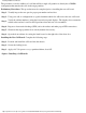
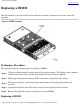
Installing the New Cell Board Complete the following steps:
Step 1. Position and install the cell board into the chassis.
Step 2. Secure the locking levers.
Step 3. Apply +48 Volt power to target partition/cabinet; boot O/S.
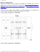
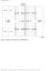
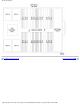
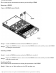
Figure 3 Installing a Cell Boards
Installing Additional Cell Boards
http://superdome-test.fc.hp.com/sd_web/content/00/0A/DV/idd/401.html (5 of 6) [03/01/2001 2:09:45 PM]